A Method for Measuring Inertial Parameters of an Infinite Model Powertrain

A powertrain and measurement method technology, applied in the field of inertial parameter measurement, can solve the problems of powertrain measurement inconvenience, etc., and achieve the effect of easy measurement and easy realization

Active Publication Date: 2022-03-18
DONGFENG AUTOMOBILE COMPANY
View PDF9 Cites 0 Cited by
  • Summary
  • Abstract
  • Description
  • Claims
  • Application Information

AI Technical Summary

Problems solved by technology

[0004] The purpose of the present invention is to overcome the problem of inconvenient powertrain measurement in the case of countless models existing in the prior art, and to provide a method for measuring inertial parameters of the infinite model powertrain

Method used


Image

  • A Method for Measuring Inertial Parameters of an Infinite Model Powertrain
  • A Method for Measuring Inertial Parameters of an Infinite Model Powertrain
  • A Method for Measuring Inertial Parameters of an Infinite Model Powertrain

Examples


Embodiment 1

[0203] A method for measuring inertial parameters of an infinite-model powertrain, the measurement method is based on the MPC700 moment of inertia test bench and its supporting measurement software, the MPC700 moment of inertia test bench includes a base 1 and a measurement table 2, the measurement table 2 located above base 1;

[0204] The top of the base 1 is provided with four moment of inertia support bases 12 and three pressure sensors 11, and the moment of inertia support base 12 can freely twist around the inner rotating shaft 13 of the base 1;

[0205] The top of the base 1 is provided with a measuring platform 2, and the top plane of the measuring platform 2 is provided with a measuring platform reference point A, a measuring platform reference point B and a measuring platform reference point C;

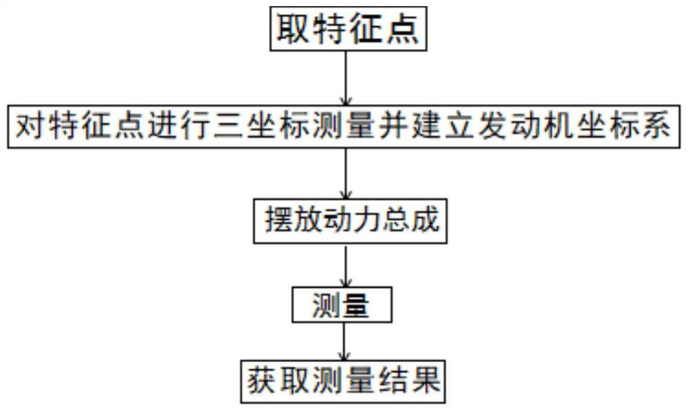
[0206] Step 1. Take feature points:

[0207] Take multiple feature points on the surface of the powertrain, and then enter step 2;

[0208] Step 2: Perform three-coordinat...

Embodiment 2

[0272] Embodiment 2 is basically the same as Embodiment 1, and its difference is:

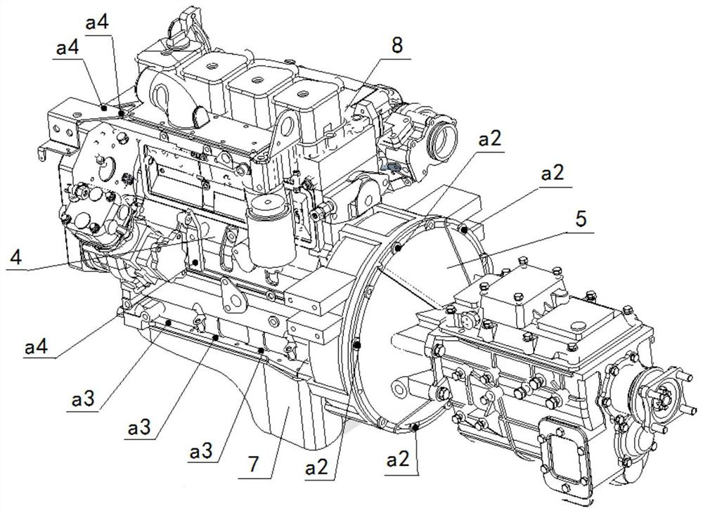
[0273] The rear end face of the cylinder block 4 in the power assembly is connected with the clutch cover 5 through a plurality of connecting bolts, and the feature point a2 of the rear end face is selected at the top of the bolt connecting the end face of the cylinder block 4 and the clutch cover 5;

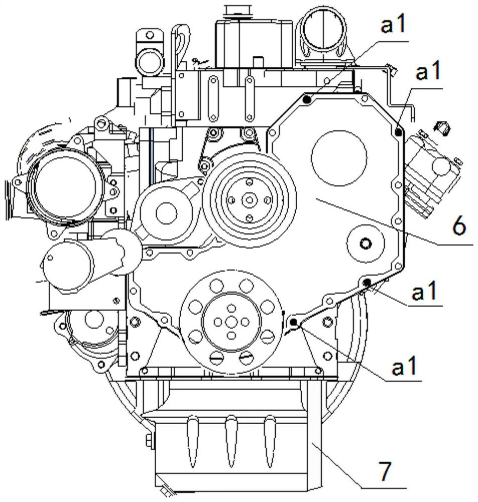
[0274] The front end face of the cylinder block 4 in the powertrain is connected with the front end cover plate 6 of the engine by connecting bolts, and the characteristic point a1 of the front end face is at the top of the bolt connecting the front end face of the cylinder block 4 and the front end cover plate 6 of the engine select.

[0275] The bottom of the cylinder block 4 in the powertrain is connected to the oil pan 7 through connecting bolts, and the upper and lower end surface feature points a3 are selected at the top of the connecting bolts connecting the engine cylinder block 4 and the...

Embodiment 3

[0278] Embodiment 3 is basically the same as Embodiment 2, and its difference is:

[0279] The feature points a3 of the upper and lower end surfaces are selected at the top of the connecting bolts on the cylinder head 8 in the powertrain.


PUM


Abstract

A method for measuring inertial parameters of an infinite-model powertrain. This measurement method is based on the MPC700 moment of inertia test bench and its supporting measurement software. The measurement method includes the following steps: taking feature points, performing three-coordinate measurement on feature points, and establishing engine coordinates system, place the powertrain, measure, and obtain measurement results. In this design, multiple characteristic points are taken on the surface of the powertrain, and three-coordinate measurement is performed on them, and the engine coordinate system is established by using some of the characteristic points, and the position of the remaining characteristic points in the engine coordinate system is measured by 3D modeling software. Coordinates, the coordinates of the feature points in the engine coordinate system are directly input in the measurement software, and the inertia parameters can be accurately measured without the digital model of the powertrain to be tested, and it is easy to implement, without the need to carry out three coordinates of the powertrain many times Measurement.

Description

technical field [0001] The invention relates to an inertial parameter measurement method, in particular to an inertial parameter measurement method of an infinite-mode power assembly, which is particularly suitable for testing the inertial parameters of an automobile power assembly under the condition of an infinite number of models. Background technique [0002] With the development of automobile technology, people pay more and more attention to the ride comfort of the car, and the NVH (vibration noise comfort) performance of the car is one of the main factors affecting the ride comfort of the car, so the NVH design has become a vehicle development important part of the. The inertial parameters of the engine include the mass of the engine, the coordinates of the center of mass, the moment of inertia and the product of inertia, which are necessary parameters for studying the dynamic characteristics of the engine, the optimal design of the suspension system, and vibration red...

Claims


Application Information

Patent Timeline
Patent Type & Authority Patents(China)
IPC IPC(8): G01B21/00G01B21/16G01M1/10G01M1/12G01B21/22G01M15/02
CPCG01B21/00G01B21/16G01M1/10G01M1/122G01B21/22G01M15/02
Inventor 宋纪侠李浩亮王彦于友明解聪吕文芬胡小文杨喜红陈文博赵建兵
Owner DONGFENG AUTOMOBILE COMPANY
Why Eureka
Try Eureka