An automatic steel bar cutting device

A cutting device and automatic cutting technology, used in metal processing equipment, metal processing, manufacturing tools, etc., can solve the problems of operator safety, low efficiency, easy scalding, etc., to reduce labor intensity, cut fast, The effect of convenient delivery

Active Publication Date: 2018-11-06
泰州市鼎阳特钢材料有限公司
View PDF10 Cites 0 Cited by
  • Summary
  • Abstract
  • Description
  • Claims
  • Application Information

AI Technical Summary

Problems solved by technology

[0003] The traditional cutting of steel bars is operated by micro-machines, and there will be flying sparks when cutting. If the protection is not timely, it will threaten the safety of the operator, and only one steel bar can be cut at a time. It is laborious, the efficiency is not high, the temperature of the newly cut steel bar is high, and it is easy to be burned if the personnel take it directly. Therefore, in order to solve these problems, it is necessary to design an automatic cutting device

Method used


Image

  • An automatic steel bar cutting device
  • An automatic steel bar cutting device
  • An automatic steel bar cutting device

Examples


Embodiment 1

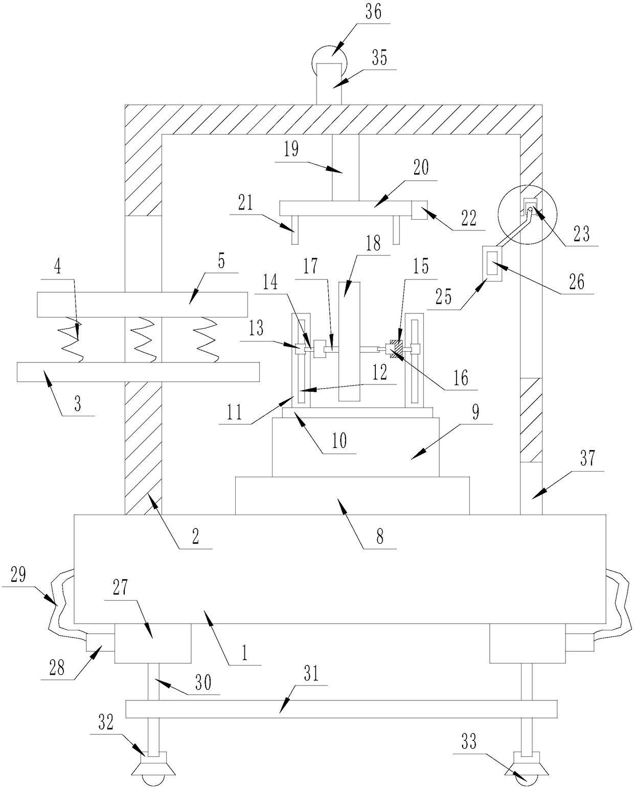
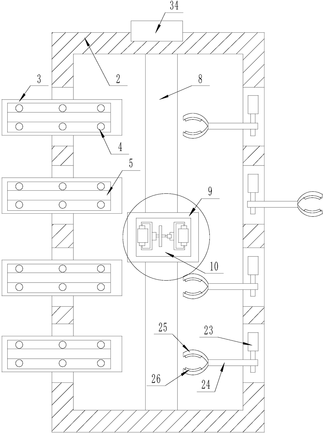
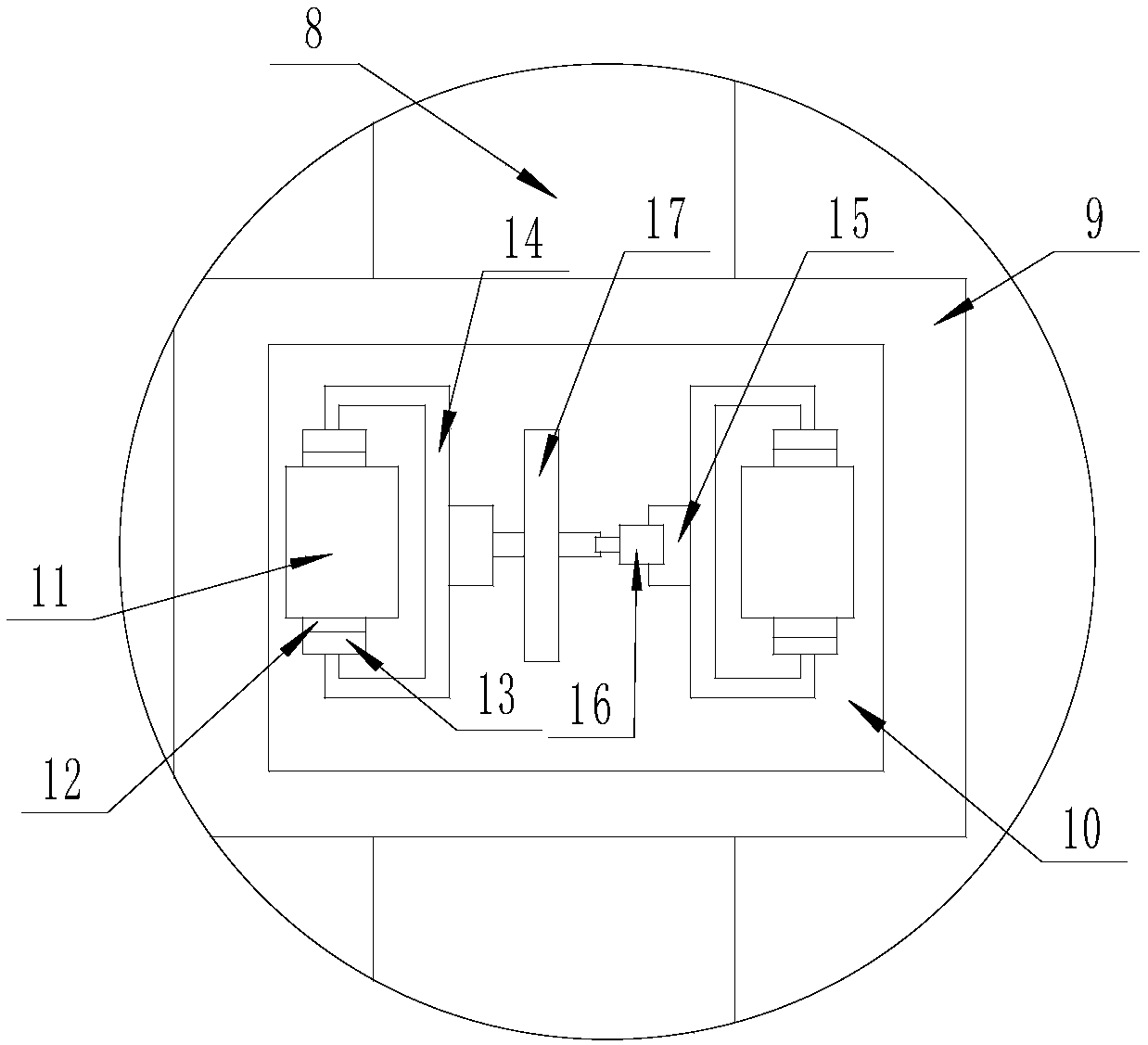
[0026] An automatic steel bar cutting device, comprising a No. 1 bar-shaped base 1, the upper surface of the No. 1 bar-shaped base 1 is fixedly connected with a bar-shaped carrying box 2, and the strip-shaped carrying box 2 is provided with automatic cutting The lower surface of the No. 1 strip base 1 is provided with a moving mechanism, the right side surface of the strip carrying box 2 is provided with a discharging mechanism, and the automatic cutting mechanism is opened on the left side of the strip carrying box 2 A plurality of No. 1 strip-shaped openings on the side surface, a No. 2 strip-shaped support plate 3 embedded in the inner lower surface of each No. 1 strip-shaped opening, a plurality of No. 2 strip-shaped support plates 3 embedded in the upper surface of each The compression spring 4, the arc-shaped carrier 5 fixedly connected to the multiple compression springs 4 on the upper surface of each No. 2 bar-shaped support plate 3, the No. 1 vertical bar-shaped openin...

Embodiment 2

[0029] Embodiment 2: The electronically controlled push rod 19 can be replaced with an electronically controlled lifting support frame, which can also achieve the lifting and lowering effect, and other structures are the same as those in Embodiment 1.


PUM


Abstract

The invention discloses an automatic rebar cutting device comprising a first strip-shaped base. A strip-shaped bearing case body is fixedly connected on the upper surface of the first strip-shaped base. An automatic cutting mechanism is arranged in the strip-shaped bearing case body. A moving mechanism is arranged on the lower surface of the first strip-shaped base. A discharging mechanism is arranged on the surface of the right side of the strip-shaped bearing case body. The automatic rebar cutting device has the beneficial effects that distance measuring is convenient, operation is easy, cutting is rapid, a plurality of rebars are cut simultaneously, the safety of personnel at the time of cutting can be protected, discharging is convenient, manual labor intensity is relieved, efficiency is improved, and moving is convenient.

Description

technical field [0001] The invention relates to the electromechanical field, in particular to an automatic steel bar cutting device. Background technique [0002] Rebar refers to steel for reinforced concrete and prestressed reinforced concrete. Its cross-section is round, sometimes square with rounded corners. Rebar cutting is the operation of cutting steel bars into desired lengths by cutting tools. . [0003] The traditional cutting of steel bars is operated by micro-machines, and there will be flying sparks during cutting. If the protection is not timely, it will threaten the safety of operators, and only one steel bar can be cut at a time. It is labor-intensive and inefficient. The temperature of the steel bar that has just been cut is high, and it is easy for personnel to scald when it is directly taken. Therefore, in order to solve these problems, it is necessary to design an automatic cutting device. SUMMARY OF THE INVENTION [0004] The purpose of the present in...

Claims


Application Information

Patent Timeline
Patent Type & Authority Patents(China)
IPC IPC(8): B21F11/00B21C51/00
CPCB21C51/00B21F11/00
Inventor 贾聪聪
Owner 泰州市鼎阳特钢材料有限公司
Why Eureka
Try Eureka