Turbofan engine assembly and method of assembling same

a technology of turbofan engine and fan assembly, which is applied in the direction of engine fuction, machine/engine, hot gas positive displacement engine plant, etc., can solve the problems of increasing the overall cost and design complexity of the turbofan engine, and operating the fan assembly at a relatively slow speed may be detrimental to the operation of the booster

Active Publication Date: 2008-05-01
GENERAL ELECTRIC CO
View PDF14 Cites 113 Cited by
  • Summary
  • Abstract
  • Description
  • Claims
  • Application Information

AI Technical Summary

Problems solved by technology

However, operating the fan assembly at a relatively slow speed may be detrimental to the operation of a booster.
As such, additional stages may be required on the booster to facilitate operating the booster at maximum efficiency, thus increasing the overall cost and design complexity of the turbofan engine.

Method used


Image

  • Turbofan engine assembly and method of assembling same
  • Turbofan engine assembly and method of assembling same
  • Turbofan engine assembly and method of assembling same

Examples


Embodiment Construction

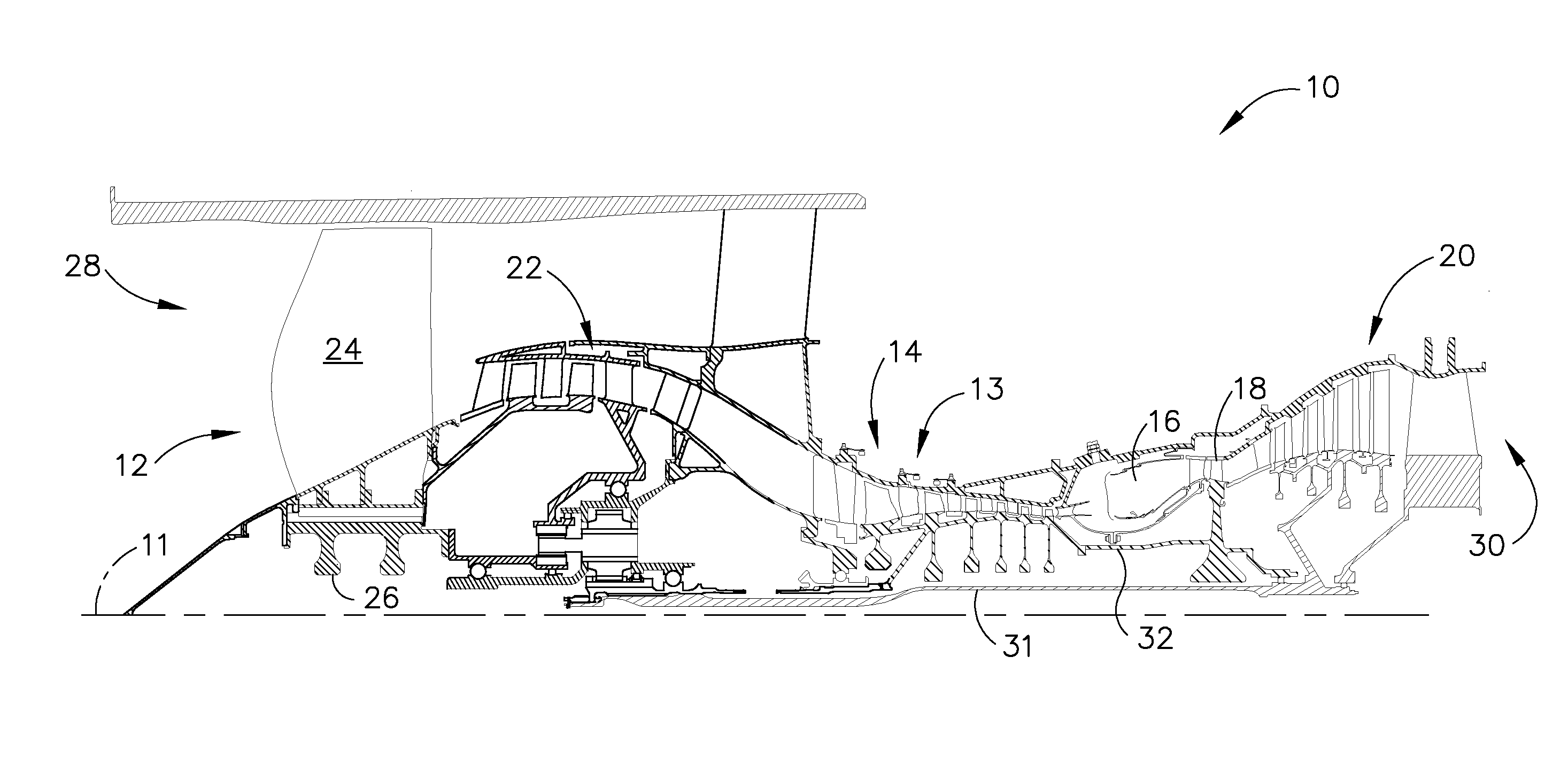
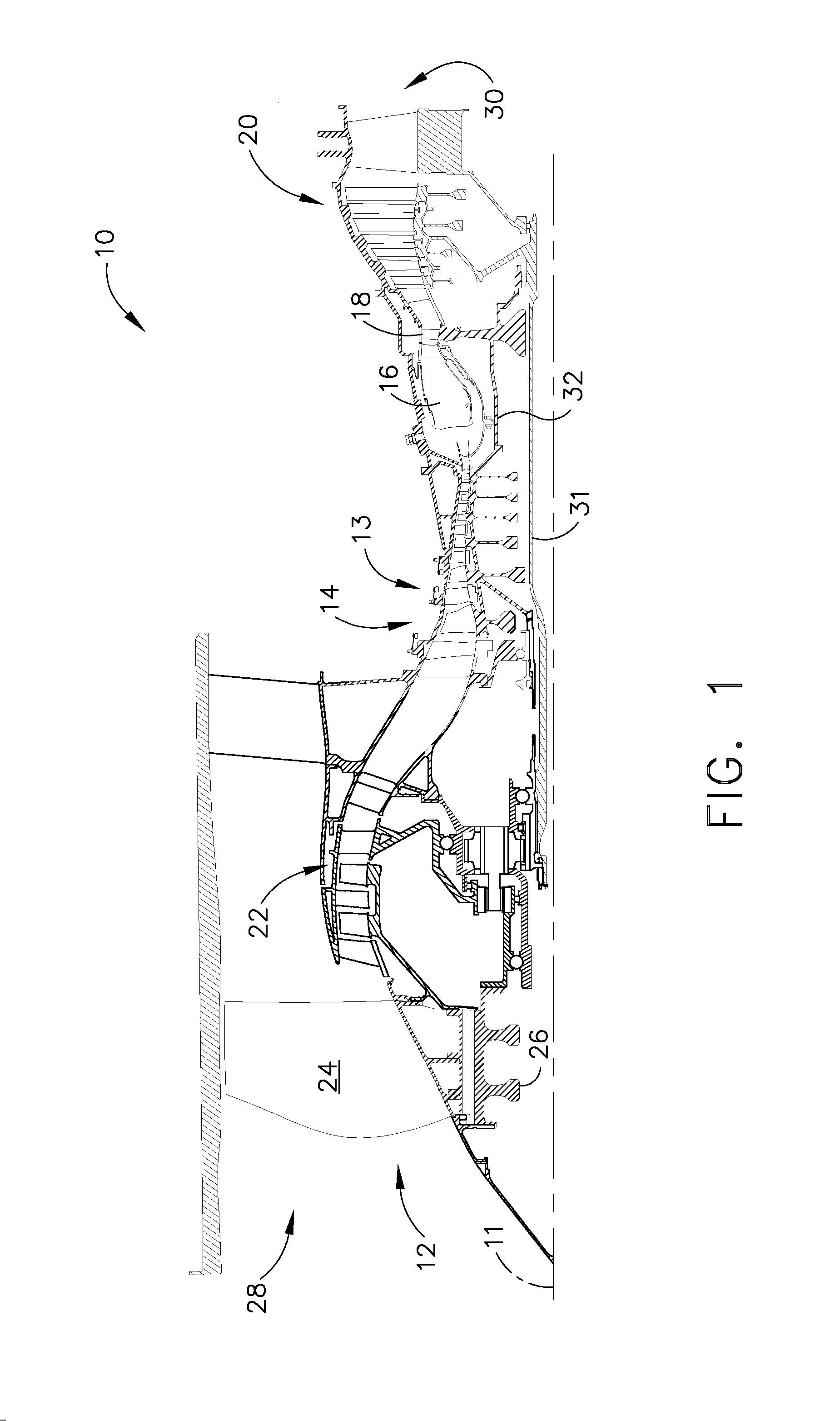
[0017]FIG. 1 is a schematic illustration of an exemplary turbofan engine assembly 10 having a longitudinal axis 11. Turbofan engine assembly 10 includes a fan assembly 12, a core gas turbine engine 13 that is disposed downstream from fan assembly 12, and a low-pressure turbine 20 that is disposed downstream from the core gas turbine engine. The core gas turbine engine includes a high-pressure compressor 14, a combustor 16, and a high-pressure turbine 18. In the exemplary embodiment, turbofan engine assembly 10 also includes a multi-stage booster compressor 22.

[0018]Fan assembly 12 includes an array of fan blades 24 extending radially outward from a rotor disk 26. Turbofan engine assembly 10 has an intake side 28 and an exhaust side 30. Compressor 14 and high-pressure turbine 18 are coupled together by a second drive shaft 32.

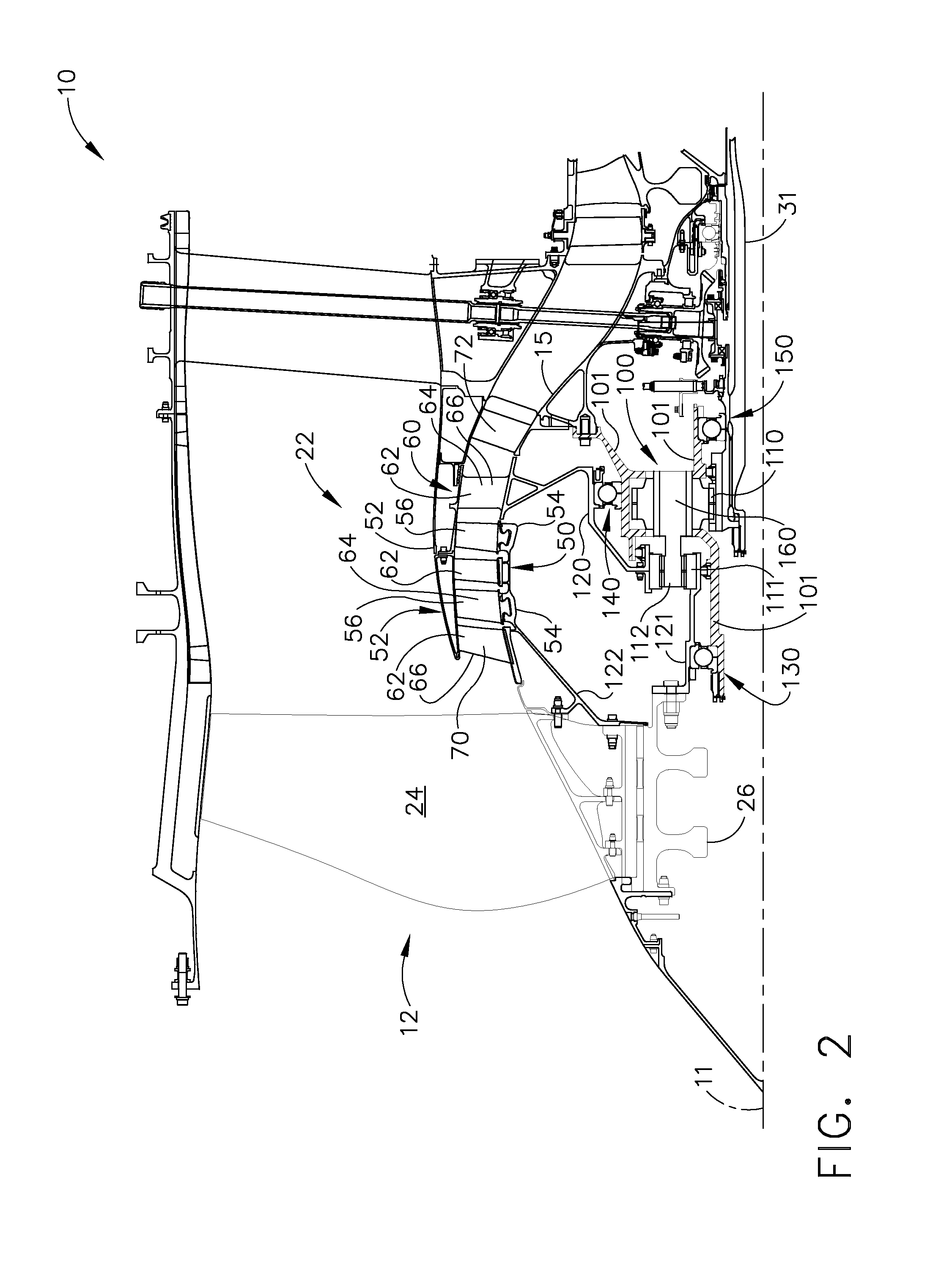
[0019]FIG. 2 is an enlarged cross-sectional view of a first booster compressor arrangement that may be utilized with turbofan engine assembly 10 shown in FIG. 1...


PUM


Abstract

A turbofan engine assembly includes a core gas turbine engine including a high-pressure compressor, a combustor, and a high-pressure turbine, a low-pressure turbine coupled to said core gas turbine engine, a counter-rotating booster compressor comprising a first rotor section configured to rotate in a first direction and a second rotor section configured to rotate in an opposite second direction, and a gearbox comprising an input and an output, said gearbox output coupled to at least one of said first and second rotor sections, said gearbox input coupled to said low-pressure turbine. A method of assembling the turbofan engine assembly described herein is also provided.

Description

BACKGROUND OF THE INVENTION[0001]This invention relates generally to gas turbine engines, and more specifically to a turbofan engine assembly that includes a counter-rotating booster compressor.[0002]At least some known turbofan engine assemblies include a fan assembly, a core gas turbine engine, and a low-pressure or power turbine. The core gas turbine engine includes at least one compressor, a combustor, and a high-pressure turbine that are coupled together in a serial flow relationship. Moreover, at least one known turbofan engine assembly includes a booster that is disposed between the fan assembly and the core gas turbine engine.[0003]To improve the efficiency of the turbofan engine assembly, it is desirable to operate the fan assembly at a relatively low speed to improve fan efficiency and to operate the high-pressure turbine at a relatively high speed to improve the high-pressure turbine efficiency. However, operating the fan assembly at a relatively slow speed may be detrime...

Claims


Application Information

Patent Timeline
Patent Type & Authority Applications(United States)
IPC IPC(8): F02K3/02
CPCF02C3/067F05D2260/40311F02C7/36
Inventor HENRY, JOHN LESLIEORLANDO, ROBERT JOSEPHMONIZ, THOMAS ORY
Owner GENERAL ELECTRIC CO
Why Eureka
Try Eureka