Self-adjusting locking pliers

a self-adjusting, locking technology, applied in the field of self-adjusting locking pliers, can solve the problems that the self-adjusting locking pliers are not all capable of generating high clamping force, and achieve the effect of reducing the actual pitch of the teeth rack, without reducing the actual pitch of the teeth, and reducing the size of the teeth

Inactive Publication Date: 2008-05-01
BLACK & DECKER INC
View PDF19 Cites 19 Cited by
  • Summary
  • Abstract
  • Description
  • Claims
  • Application Information

AI Technical Summary

Benefits of technology

[0006]The locking slidable pivot connection includes a pawl secured to the moveable jaw by a first pivot where the pivot and pawl are moveable within a slot formed in the body. The pawl may be provided with forwardly facing teeth for engaging a rack of teeth on a front edge of the slot for providing selective engagement therebetween. The pawl is normally disengaged from the rack and engages the rack when the jaws contact a work piece. The rack of teeth may include a first set of teeth and a second set of teeth extending parallel to one another along the front edge of the slot. The first set of teeth and the second set of teeth may each be engaged by the pawl teeth. The teeth of the first set of teeth may be offset from the teeth of the second set of teeth by up to ½ of the pitch. As a result, the pitch of the rack of teeth is effectively reduced by one-half without making the teeth smaller or reducing the actual pitch of the teeth. One pawl may engage the first set of teeth a tooth higher or lower than the other pawl engages the second set of teeth such that the effective pitch is one-half the actual tooth pitch.
[0007]A linkage is provided that connects the movable jaw, operating lever and body so as to transmit a force applied to the handles of the pliers to the jaws and to lock the jaws in the clamping position on the work piece. The linkage allows the angle between the links to be preset to thereby control the clamping force applied to the work piece. The linkage also allows the preset clamping force to be maintained on different work pieces through repeated clamping and unclamping operations of the pliers.

Problems solved by technology

Self-adjusting locking pliers are not all capable of generating the high clamping forces that are expected of locking pliers and some designs are susceptible to back drive forces that can inadvertently force open the pliers under high loads.

Method used


Image

  • Self-adjusting locking pliers
  • Self-adjusting locking pliers
  • Self-adjusting locking pliers

Examples


Embodiment Construction

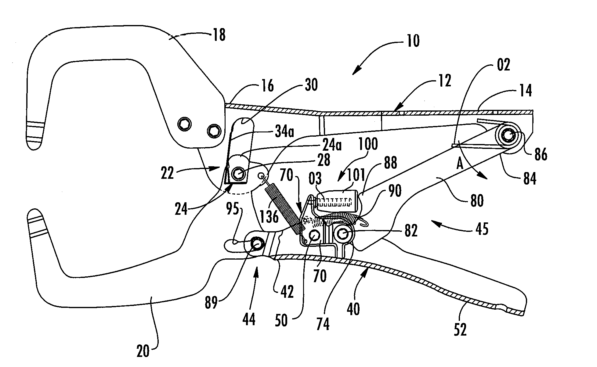
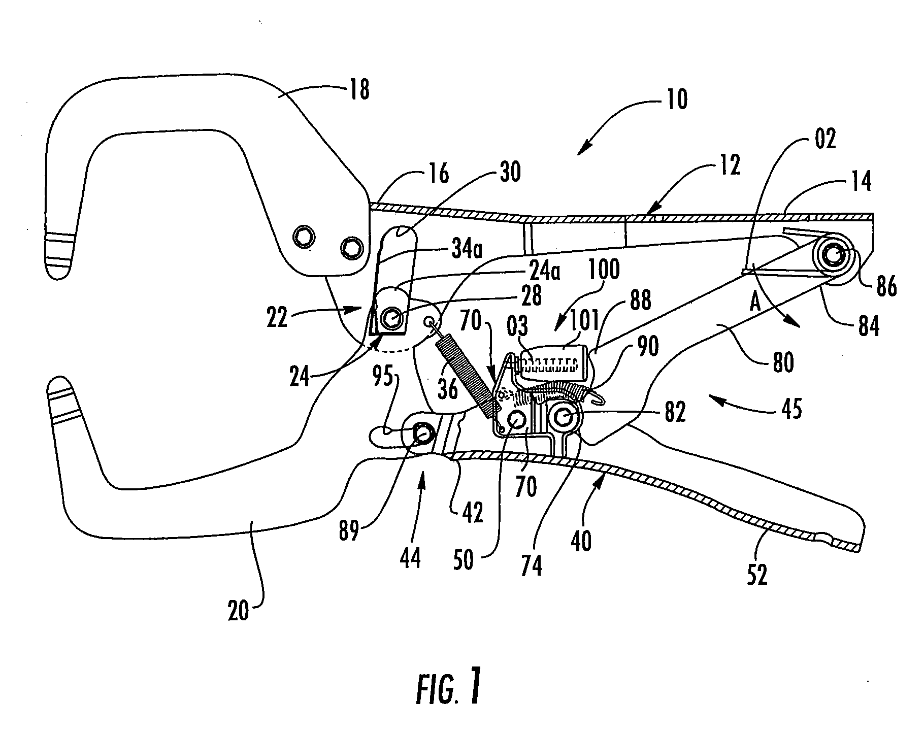
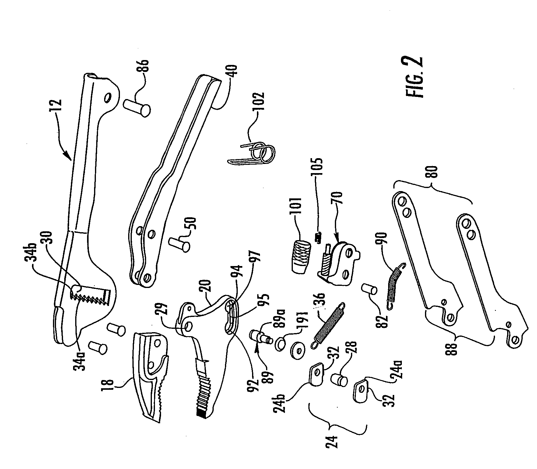
[0016]Referring to the Figures, an embodiment of the self-adjusting locking pliers 10 of the invention is shown comprising a fixed assembly including a body 12 having a fixed handle 14 at one end thereof. The other end 16 supports a fixed plate or jaw 18. The fixed jaw 18 may be made integrally with the body 12 or may be a separate member rigidly connected with the body. In the illustrated embodiment the body 12 is shown as a separately identifiable element from fixed jaw 18. Where the body 12 and fixed jaw 18 are formed integrally with one another, a clear line of demarcation may not be visible between these elements such that elements disclosed herein as being arranged on the body may in some embodiments be arranged on a portion of the jaw structure or on a transition area between the jaw and body. The jaws 18 and 20 shown in the embodiments of FIGS. 1 through 5 are large jaws suitable for use as a clamp while the jaws 19 and 21 shown in the embodiment of FIG. 6 are jaws suitable ...


PUM


Abstract

The self-adjusting locking pliers include a body having a fixed jaw supported at one end. A moveable jaw is pivotably supported on the body at a slidable pivot connection. A linkage transmits a force applied to the handles of the pliers to the jaws and locks the jaws in the clamping position. The linkage allows the angle between the links to be preset to thereby control the clamping force applied to the work piece. The movable jaw is selectively attached to the linkage in one of two positions such that the jaw span may be adjusted without affecting the geometry of the linkage.

Description

[0001]This invention relates to pliers, and more particularly, to self-adjusting locking pliers that enable the clamping force generated by the device to be pre-set.BACKGROUND OF THE INVENTION [0002]Self-adjusting or auto-adjusting pliers are known. Such pliers have jaws which are self-adjusting accordingly to the size of the work piece to be grasped between the jaws. Examples of such self-adjusting pliers are disclosed in U.S. Pat. No. 6,065,376 and U.S. Pat. No. 6,279,431.[0003]Also known are locking pliers which incorporate an over-center compound toggle locking mechanism or linkage whereby when the moveable jaw of the pliers is adjusted to seize a work piece firmly between the moveable and the fixed jaw and the handles are tightly compressed, the toggle mechanism locks the hand tool onto the work piece. Examples of this type of pliers are disclosed in U.S. Pat. No. 5,056,385 and U.S. Pat. No. 6,626,070 (locking pliers sold under the trademark VISE-GRIP).[0004]Self-adjusting lock...

Claims


Application Information

Patent Timeline
Patent Type & Authority Applications(United States)
IPC IPC(8): B25B7/12
CPCB25B7/04B25B7/123B25B7/10
Inventor ENGVALL, DAVID P.CHERVENAK, THOMAS M.
Owner BLACK & DECKER INC
Why Eureka
Try Eureka