Turbine inlet air treatment apparatus

Inactive Publication Date: 2008-05-01
GENERAL ELECTRIC CO
View PDF9 Cites 137 Cited by
  • Summary
  • Abstract
  • Description
  • Claims
  • Application Information

AI Technical Summary

Benefits of technology

[0006]The present application thus describes an inlet air treatment system. The inlet air treatment system includes a housing with more than two symme

Problems solved by technology

Impure air laden with dust particles, salt and other contaminants may damage the compressor blades and other types of power plant equipment via corrosion and/or erosion.
Such damage may reduce the life expectancy and the performance of the equipment.
These known filtration systems, however, may be complicated and costly.
These restrictions, however, may limit the amount of air that can be filtered.
Known air filters al

Method used


Image

  • Turbine inlet air treatment apparatus
  • Turbine inlet air treatment apparatus

Examples


Embodiment Construction

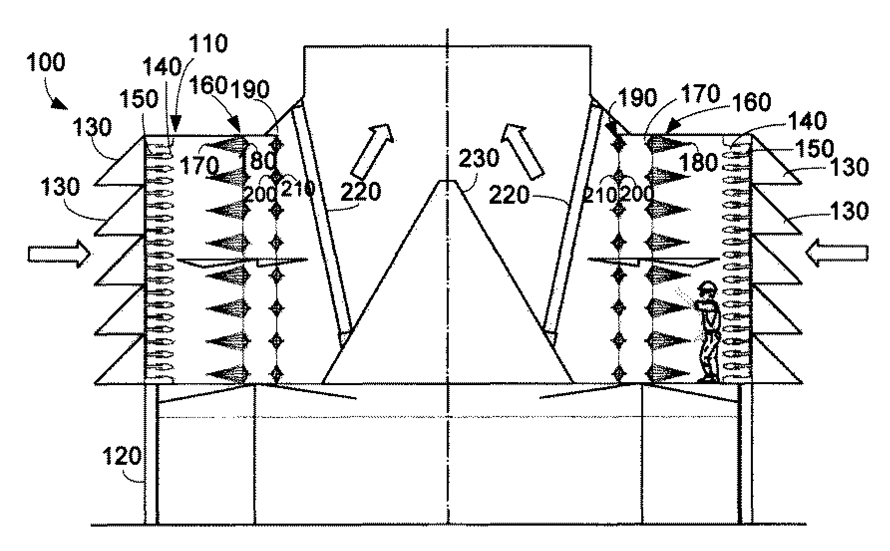
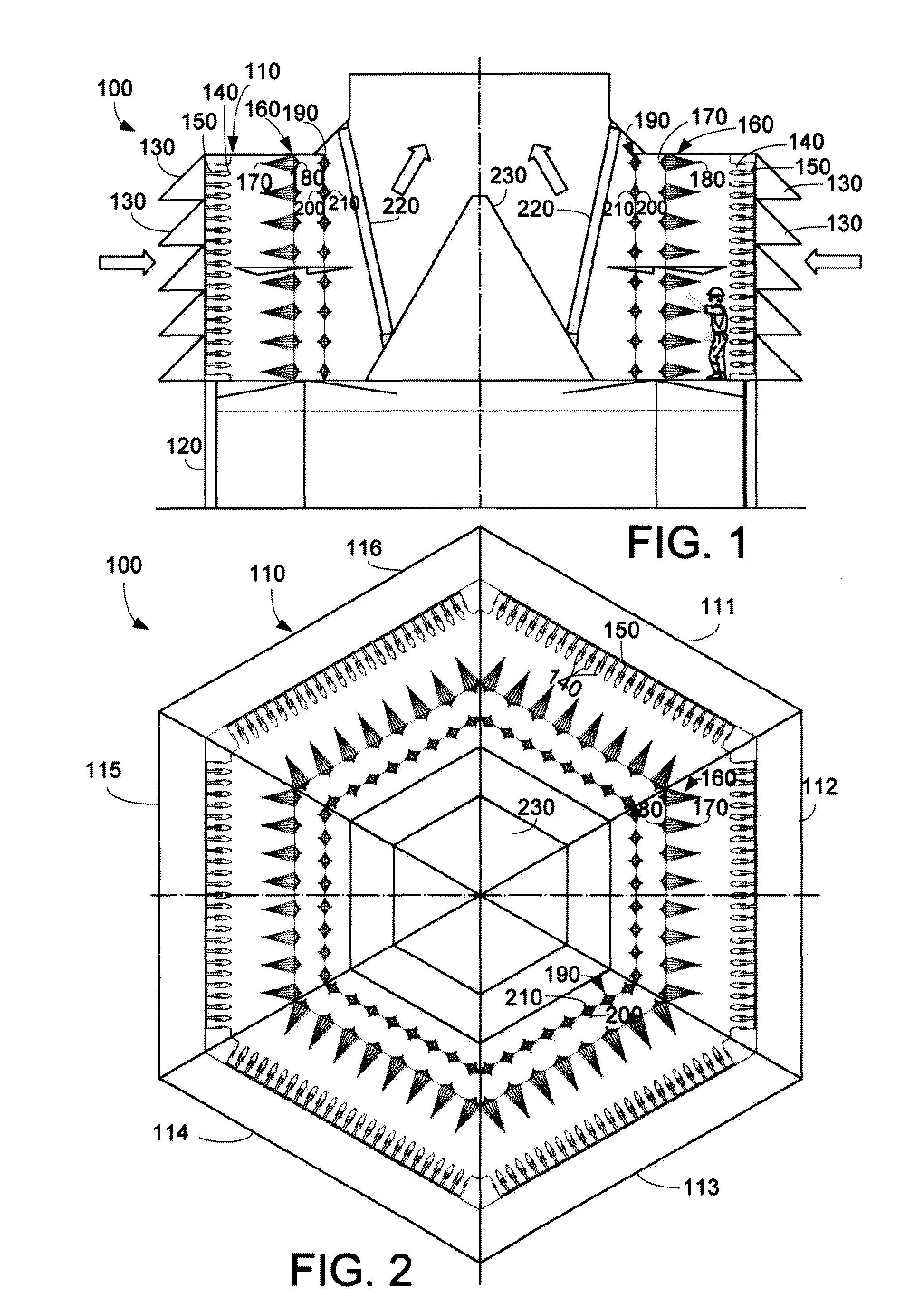
[0012]Referring now to the drawings, in which like numerals indicate like elements throughout the several views, FIGS. 1 and 2 show schematic views of a turbine inlet air treatment system 100 as is described herein. As described above, the turbine inlet air treatment system 100 may be positioned upstream of a compressor or other type of turbine component.

[0013]The air treatment system 100 includes a housing 110. The housing 110 may be made out of any type of conventional material so as to mount the components described below therein. The housing 110 may have a number of structural supports 120 such that the system 100 may be positioned at any desired height. The structural supports 120 also may be made out of any conventional type of material. As is shown, the housing 110 has a symmetric hexagonal configuration with first side 111, second side 112, third side 113, fourth side 114, fifth side 115, and sixth side 116. Similar types of symmetric and near symmetric configurations may be...


PUM

PropertyMeasurementUnit
Angleaaaaaaaaaa
Shapeaaaaaaaaaa

Abstract

An inlet air treatment system. The inlet air treatment system includes a housing with more than two symmetric sides. Each of the sides includes a number of air filters and a number of spray arrays. A central air deflector is positioned within the housing.

Description

TECHNICAL FIELD[0001]The present application relates generally to gas turbine engines and more particularly relates to a polar-symmetric combustion turbine inlet air treatment apparatus.BACKGROUND OF THE INVENTION[0002]Air entering a turbine compressor and similar devices should be filtered before compression or other use. Impure air laden with dust particles, salt and other contaminants may damage the compressor blades and other types of power plant equipment via corrosion and / or erosion. Such damage may reduce the life expectancy and the performance of the equipment. To avoid this problem, the inlet air generally passes through a series of air filters to remove the contaminants. Such air filters generally are located at an elevated height so as to minimize the entry of ground contaminants. These known filtration systems, however, may be complicated and costly.[0003]Conventional inlet air filters generally have air velocity restriction therethrough so as to maintain filtration and ...

Claims


Application Information

Patent Timeline
IPC IPC(8): B01D47/00
CPCF02C3/30F02C7/04F05D2250/132F05D2240/40F05D2250/232F02C7/052F01D25/00F02C7/05F02C7/055
Inventor FEHER, PETERMOTAKEF, ABBAS
Owner GENERAL ELECTRIC CO
Why Eureka
Try Eureka