
Radio frequency identification of component connections

a component connection and radio frequency identification technology, applied in the direction of burglar alarm mechanical actuation, burglar alarm by hand-portable object removal, instruments, etc., can solve the problems of rfid system drawbacks, difficulty or inaccurate, and inability to identify proper plugs and sockets for setting up and maintaining systems accordingly

Active Publication Date: 2008-05-01
FIBER MOUNTAIN INC
View PDF99 Cites 176 Cited by
  • Summary
  • Abstract
  • Description
  • Claims
  • Application Information

AI Technical Summary

Benefits of technology

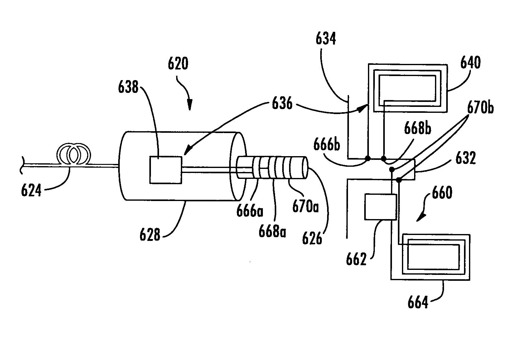
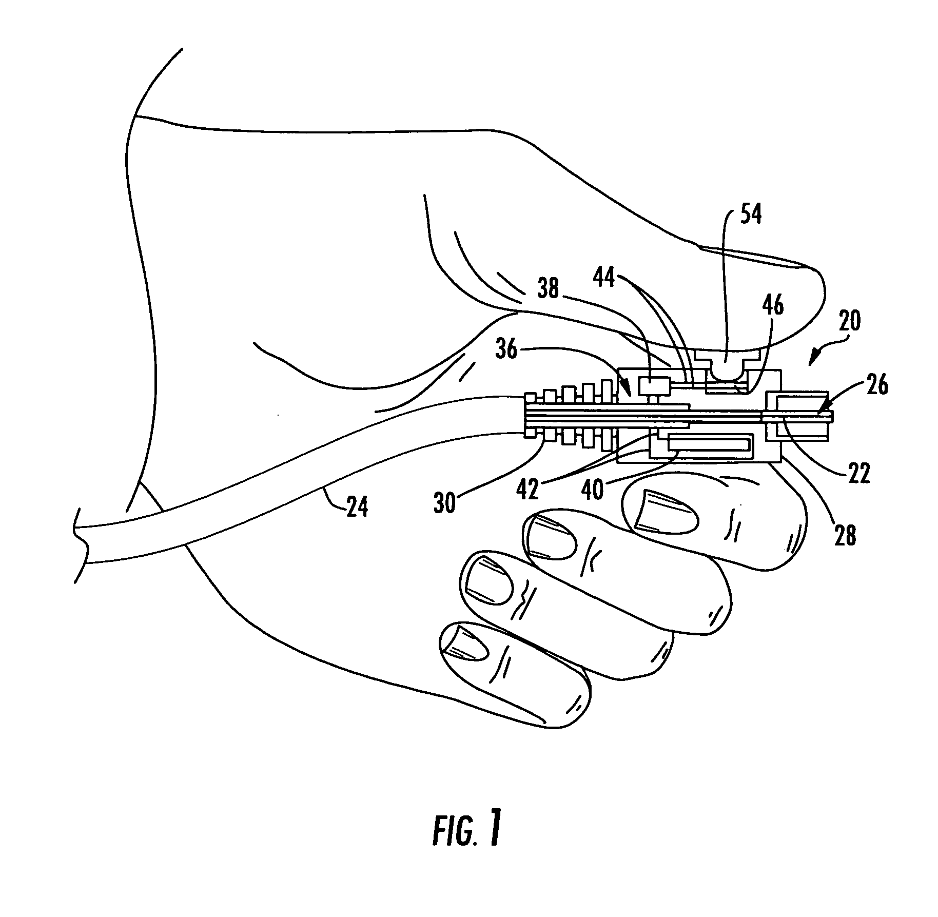
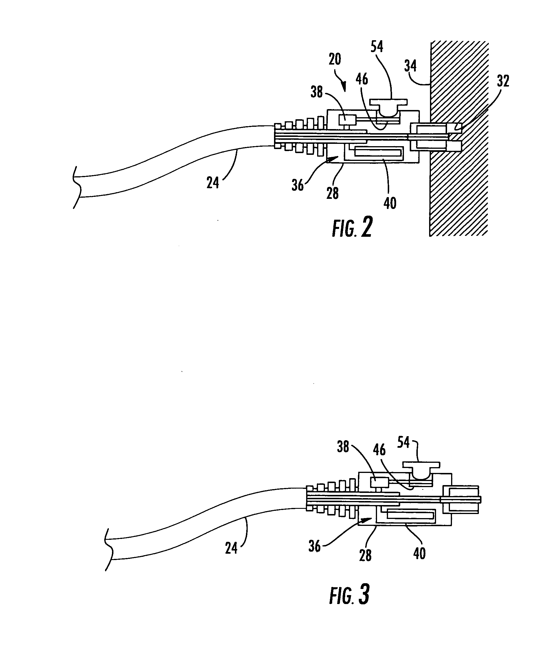
[0011]According to certain embodiments of the present invention, a system of identifying, via an RFID reader, a connection of two or more components is provided. The system includes a plug associated with a first component and a socket associated with the second component, and a pair of contact points is associated with at least one of the plug and socket. A plug RFID transponder is associated with the plug, and a socket RFID transponder is associated with the socket. One or both of the plug RFID transponder and the socket RFID transponder is activatable when the plug is received by the socket such that a portion of the respective plug RFID transponder and the socket RFID transponder contact the pair of contact points. The RFID reader is able to identify the plug and socket based upon an RFID signal communicated by the plug RFID transponder and/or the socket RFID transponder. Further embodiments of the present invention that may or

Problems solved by technology

As fiber optic equipment and networks become more common and more complex, the identification of proper plugs and sockets (into which the plugs are mated) for setting up and maintaining the systems accordingly becomes more complex.
However, such RFID systems have certain drawbacks.
For example, the operation of such systems is dependent upon the relative proximity to a targeted item, which can lead to either difficult or inaccurate results, as signals may be received and / or communicated by unintended RFID transponders on items near the targeted item.
Accordingly, the read range of a given RFID reader, whether incorporated into the socket housing or remote, can be a limiting factor.
Further, if a plug were only partially inserted into a socket so as not to make a functional connection with the optical fiber(s), the RFID antennas in the plug and / or socket might inaccurately indicate the connection were made due to the proximity between the plug and the socket.
Moreover, when dealing with an entire panel of connectorized cables and sockets, it may not be practical or even possible to rely upon proximity, either plug-to-socket or reader-to-transponder, as a method of querying a targeted RFID transponder.
In fact, the RFID transponders across the entire panel could respond to an RFID reader in certain situations, thereby providing no useful information as to identification of individual plugs and / or sockets of interest.
In such situations, a craftsman may need to separate a plug from the socket and panel to obtain information from the RFID transponder of the plug or socket, thereby breaking the fiber optic connection in the process.
Such serial disconnection can be even more undesirable when equipment is operating and disconnections cause problems for the users of the systems.
The process becomes more complex when extended to entire networks including multiple equipment housings, cables, etc., perhaps spread throughout a building.
It can also be difficult for the craftsman in the field to determine how or why a plug, cable, socket, or the like has failed or otherwise needs replacing.
Again, identification of a single item within a group can be difficult, as well as identifying conditions leading to a particular issue.

Method used


Image

  • Radio frequency identification of component connections
  • Radio frequency identification of component connections
  • Radio frequency identification of component connections

Examples


Embodiment Construction

[0029]Reference will now be made in detail to the present preferred embodiments of the invention, examples of which are illustrated in the accompanying drawings. Whenever possible, like or similar reference numerals will be used throughout the drawings to refer to like or similar parts. The exemplary embodiments of the invention employ RFID technology to allow for simple, reliable, and / or unobtrusive identification of one or more components, including identification of location and past and / or present condition. It should be understood that the embodiments disclosed herein are merely examples, each incorporating certain benefits of the present invention. Various modifications and alterations may be made to the following examples within the scope of the present invention, and aspects of the different examples may be mixed in different ways to achieve yet further examples. Accordingly, the true scope of the invention is to be understood from the entirety of the present disclosure, in ...


PUM


Abstract

There is provided a system for identifying a connection of two or more components in which one or more RFID transponders are associated with the two or more components. A plug is associated with the first component, such as a fiber optic connector, and a socket is associated with the second component, such as a fiber optic adapter. An RFID transponder is associated with each component and at least one of the RFID transponders is activatable when the plug is received by the socket to enable the activated RFID transponder to communicate with the RFID reader. The antennas and integrated circuit chips that define the RFID transponders are positioned relative to the plug and socket to enable the one or more RFID transponders to activate when the plug is received by the socket. In addition, the RFID transponders may communicate with one another to identify other RFID transponders in order to communicate identities of two or more RFID transponders.

Description

FIELD OF THE INVENTION[0001]The present invention relates generally to use of Radio Frequency Identification (RFID) devices with two or more connectable components. More particularly, the present invention relates to the use of one or more RFID transponders to identify a connection of two or more components, such as components of telecommunications equipment.BACKGROUND OF THE INVENTION[0002]Fiber optic cables are well known for connecting optical devices and systems. Some cables carry multiple fibers and have one or more plugs, such as connectors. “Pre-connectorized” cables have their connectors attached during manufacture, while others are terminated and have connectors attached upon installation. Cables known as patch cables, jumper cables, and break out cables are often relatively short and have one or more connectors at each end. In use, each connector will be placed within a port located in a piece of equipment, patch panel, another connector, etc.[0003]As fiber optic equipment...

Claims


Application Information

Patent Timeline
IPC IPC(8): G08B21/00G08B13/14
CPCG02B6/3895G06K19/07345G06K19/0723G06K19/0717
Inventor DOWNIE, JOHN D.HEMENWAY, BREWSTER R.SUTHERLAND, JAMES S.TAYLOR, MARK P.WHITING, MATTHEW S.WAGNER, RICHARD E.
Owner FIBER MOUNTAIN INC
Learn More