
Radar apparatus and radar picture display method

a technology of radar and display method, applied in the field of radar apparatus, can solve the problems of deteriorating range discrimination, conventional radar apparatus showing this drawback, and inability to discriminate between nearby targets

Active Publication Date: 2008-05-01
FURUNO ELECTRIC CO LTD
View PDF7 Cites 27 Cited by
  • Summary
  • Abstract
  • Description
  • Claims
  • Application Information

AI Technical Summary

Benefits of technology

[0014]In light of the aforementioned problems of the prior art, it is an object of the invention to provide a correct on-screen presentation of motion-related information on each tracked target. It is another object of the invention to provide a radar apparatus having an integral ARPA function and a radar picture display method which make it possible to present the same motion-related information on each tracked target on all range scales in use without ARPA tracking errors even when the radar apparatus is operated in a mode in which multiple radar pictures obtained with different transmission pulselengths are simultaneously displayed on a single screen.
[0019]In another feature of the invention, the ARPA processor selects one of the echo signals obtained with the different pulselengths according to the distance from own ship position and produces the aforementioned motion-related information on each tracked target to be superimposed on the display echo data by using the selected echo signal. Since the ARPA processor selectively processes the echo signals obtained with the different pulselengths in this way, it is possible to reduce computational complexity by approximately half compared to a case where the ARPA processor generates plural sets of motion-related information on each tracked target from the echo signals obtained with the individual pulselengths.
[0024]According to the present invention, the radar apparatus generates uniquely defined motion-related information on each tracked target to be superimposed on the display echo data on each range scale by using the echo signals obtained with different transmission pulselengths. It is therefore possible to present the same motion-related information on the same tracked target even when plural radar pictures are simultaneously displayed on different range scales.
[0025]Additionally, the ARPA processor gives priority to such pieces of motion-related information that are derived from an echo signal obtained with a short pulselength which produces higher range discrimination for any tracked targets located close to own ship, so that it is possible to provide more detailed motion-related information on the tracked targets. This is particularly advantageous in avoiding presentation of incorrect motion-related information which will result from poor range discrimination on a longer range scale due to the use of a longer transmission pulselength.

Problems solved by technology

If the transmission pulselength is lengthened to improve long-range target detectability, however, the range discrimination deteriorates.
Thus, there arises a problem that nearby targets can not be discriminated from one another when these targets are observed on a long range scale.
The conventional radar apparatus exhibits this drawback most conspicuously particularly when viewing nearby targets on a long range scale.
Therefore, the zoom function does not provide any solution to the aforementioned drawback of the conventional radar apparatus.
The aforementioned technique of Japanese Patent Application Publication No. 1992-98179 and Japanese Patent No. 3507717, if implemented in an ARPA, poses a problem that the result of acquisition and tracking of the same target would differ depending on which one of the multiple pulselengths is used.
This is because echoes of two nearby targets which are separated from each other on a short pulselength can merge into a single target echo when the ARPA is switched to a long pulselength which results in a poor range discrimination.
Especially when the ARPA is operated in a mode in which multiple radar pictures obtained with different pulselengths are simultaneously displayed on a single screen, the ARPA function will provide different results for the targets detected with the short pulselength and the targets detected with the long pulselength, thereby causing confusion to the user.

Method used


Image

  • Radar apparatus and radar picture display method
  • Radar apparatus and radar picture display method
  • Radar apparatus and radar picture display method

Examples


first embodiment

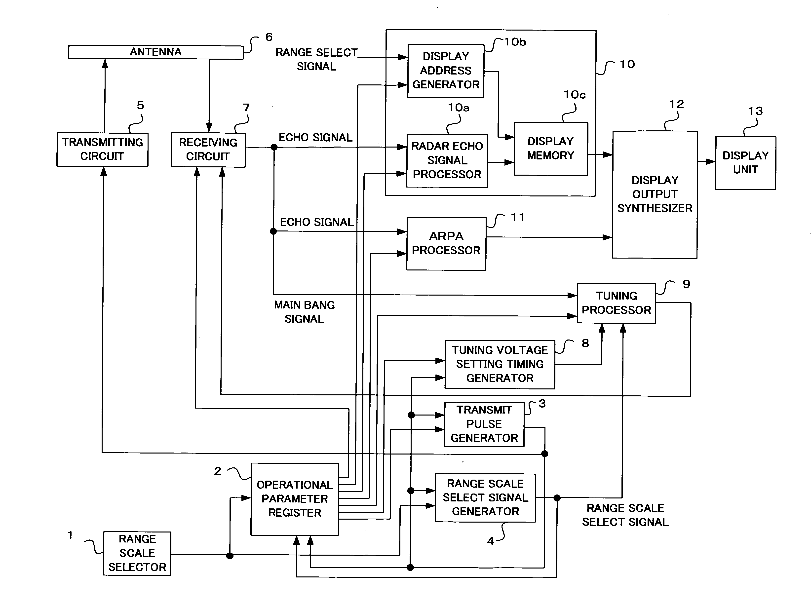
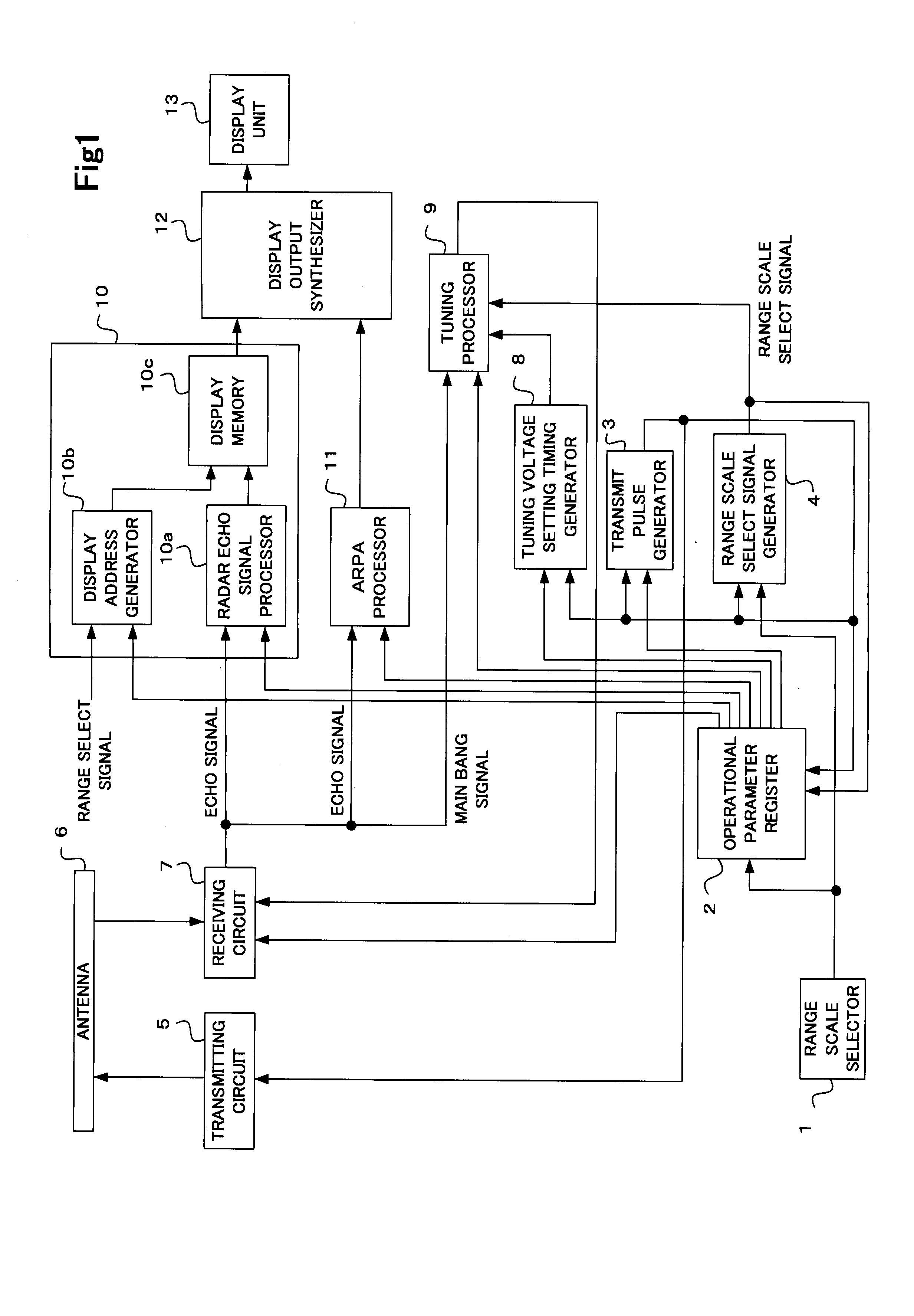
[0035]FIG. 1 is a block diagram showing the configuration of a radar apparatus having an integral ARPA function according to a first embodiment of the invention. As shown in FIG. 1, the radar apparatus of the first embodiment includes a range scale selector 1, an operational parameter register 2, a transmit pulse generator 3, a range scale select signal generator 4, a transmitting circuit 5, an antenna 6, a receiving circuit 7, a tuning voltage setting timing generator 8, a tuning processor 9, an echo data generator 10, an ARPA processor 11, a display output synthesizer 12 and a display unit 13.

[0036]The range scale selector 1 determines a range scale for on-screen presentation in accordance with an operator input. If the operator intends to simultaneously present a pair of radar pictures on two different range scales, the operator selects a dual-picture display mode and the two range scales for on-screen presentation by manipulating appropriate operating controls, such as keys or k...

second embodiment

[0083]A radar apparatus having an integral ARPA function according to a second embodiment of the invention is now described with reference to FIGS. 6A, 6B and 7, in which elements like those of the first embodiment are designated by the same symbols and a description of such elements are not given below again.

[0084]The radar apparatus of the second embodiment is characterized in that an ARPA processor 11 selects one of echo signals obtained with different transmission pulselengths according to the distance from own ship position and produces motion-related information on tracked targets to be superimposed on display echo data by using the selected echo signal.

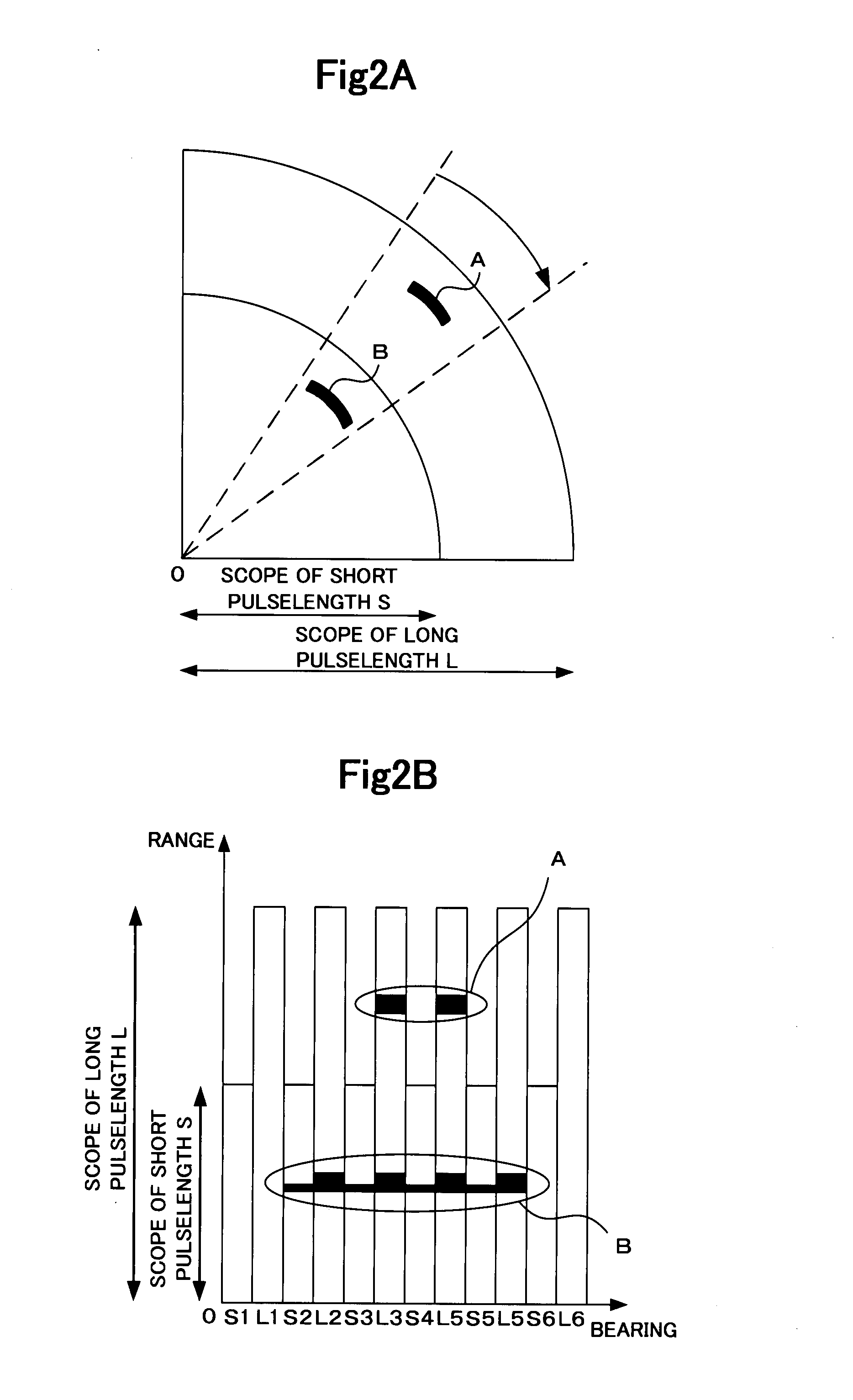
[0085]FIGS. 6A and 6B are diagrams showing how an echo detector 21c of the ARPA processor 11 works in the radar apparatus of the second embodiment. Shown in FIGS. 6A and 6B is an example in which the radar apparatus alternately transmits pulse signals having two different pulselengths, that is, the pulse signal having a short p...


PUM


Abstract

A radar apparatus having an integral ARPA function transmits at least two kinds of pulse signals, each of which has different pulselength, according to a specific transmission pattern and receives echoes of the transmitted pulse signal. The radar apparatus includes an echo data generator for generating display echo data for each range scale selected for on-screen presentation by using an echo signal obtained with each transmission pulselength, an ARPA processor for generating a single set of motion-related information on each tracked target to be superimposed on the display echo data by using echo signals obtained with the different pulselengths, a display output synthesizer for superimposing the motion-related information on each tracked target generated by the ARPA processor on the display echo data, and a display unit for displaying a superimposed picture produced by the display output synthesizer.

Description

CROSS REFERENCE OF RELATED APPLICATION[0001]Japanese Patent Application Tokugan No 2006-163914 is hereby incorporated by reference.BACKGROUND OF THE INVENTION[0002]1. Field of the Invention[0003]The present invention relates generally to a radar apparatus and, more particularly, to an Automatic Radar Plotting Aid (ARPA) configured based on a radar apparatus which transmits and receives signals having different pulselengths assigned individually to plural range scales in use through a single antenna.[0004]2. Description of the Related Art[0005]A radar apparatus conventionally used on a ship, for instance, transmits a specific pulse signal and receives an echo signal reflected by surrounding targets through an antenna. The radar apparatus determines angular direction, or bearing (θ), of a particular target from the direction of the antenna as well as a range (r) to the target based on the time elapsed from transmission of the pulse signal to reception of the echo signal.[0006]The puls...

Claims


Application Information

Patent Timeline
Patent Type & Authority Applications(United States)
IPC IPC(8): G01S13/00G01S13/937
CPCG01S7/064G01S7/12G01S13/9307G01S13/103G01S13/106G01S7/22G01S13/937
Inventor YANAGI, KATSUYUKIDAI, KOJITAKEMOTO, SAE
Owner FURUNO ELECTRIC CO LTD
Learn More