Electronic device providing tactile feedback

a technology of tactile feedback and electronic devices, applied in the field of electronic devices, can solve the problems of not allowing selective feedback to individual input locations (keys, buttons, arrows, etc.), and achieve the effect of low cos

Inactive Publication Date: 2008-05-01
MOTOROLA INC
View PDF10 Cites 172 Cited by
  • Summary
  • Abstract
  • Description
  • Claims
  • Application Information

AI Technical Summary

Benefits of technology

[0007]An electronic device provides tactile feedback provided by a low cost, thin piezoelectric device giving tactile feedback emulating a click-like feel. The apparatus comprises a chassis plate having a periphery secured to a housing and comprises a flexible material having a first planar side, and a second planar side opposed to the first planar side. An input device has a planar side positioned adjacent to and in contact with to the first planar side of the chassis. One or more piezoelectric actuators are secured to the second planar side and within the periphery of the chassis plate. Electronic circuitry positioned within the housing drives the piezoelectric actuator in response to a user actuating the input device. An input provided to the input device is sensed by the electronic circuitry. The circuitry provides a voltage waveform to activate the one or more piezoelectric actuators, which flexes the chassis plate and the input device to emulate the click like feed. A second exemplary embodiment positions the piezoelectric actuators between the chassis plate and the input device.

Problems solved by technology

This mechanism is great for providing a “call alert” for example, but does not allow for selective feedback to individual input locations (keys, buttons, arrows, etc).

Method used


Image

  • Electronic device providing tactile feedback
  • Electronic device providing tactile feedback
  • Electronic device providing tactile feedback

Examples


Embodiment Construction

[0016]The following detailed description of the invention is merely exemplary in nature and is not intended to limit the invention or the application and uses of the invention. Furthermore, there is no intention to be bound by any theory presented in the preceding background of the invention or the following detailed description of the invention.

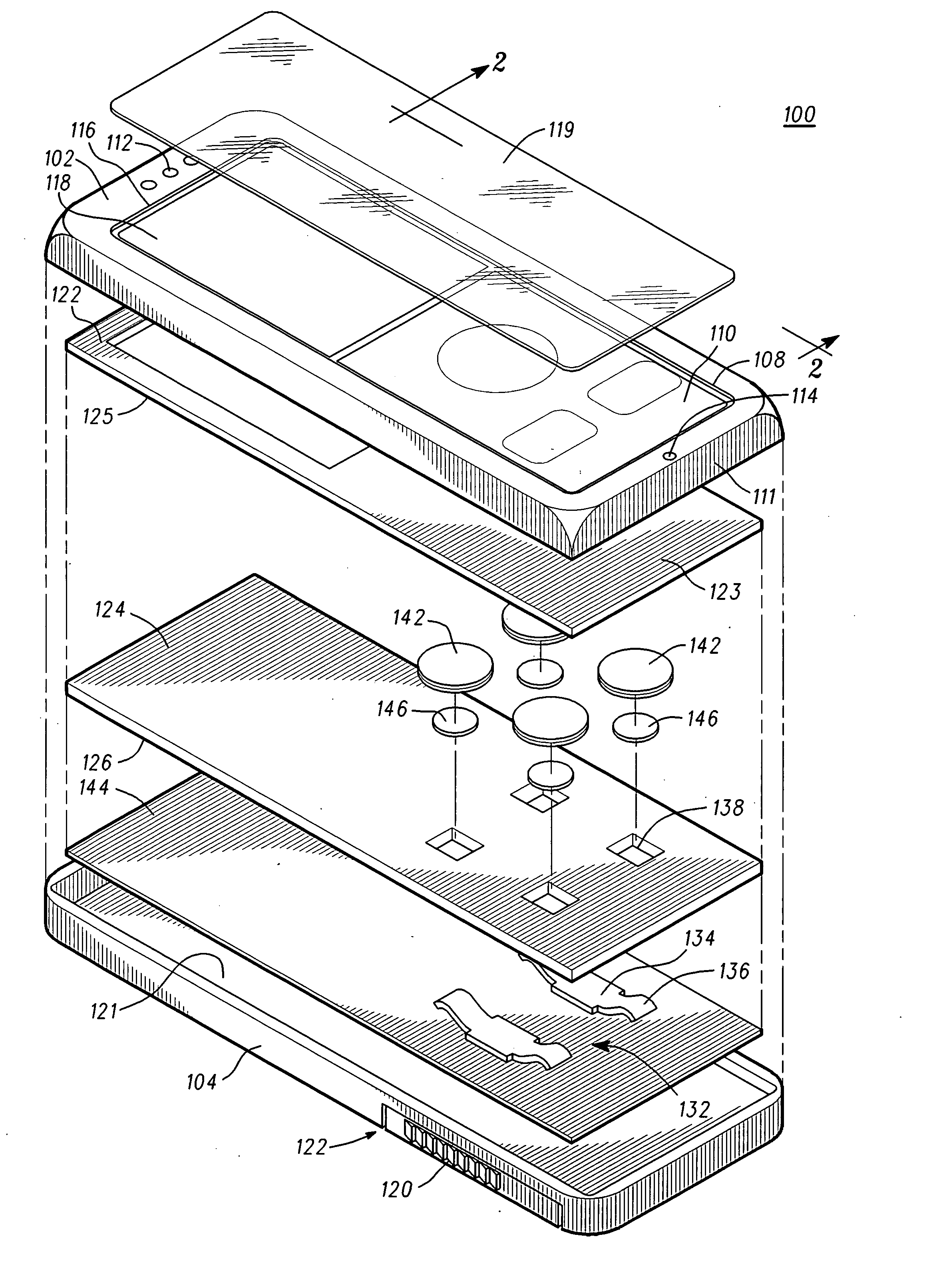
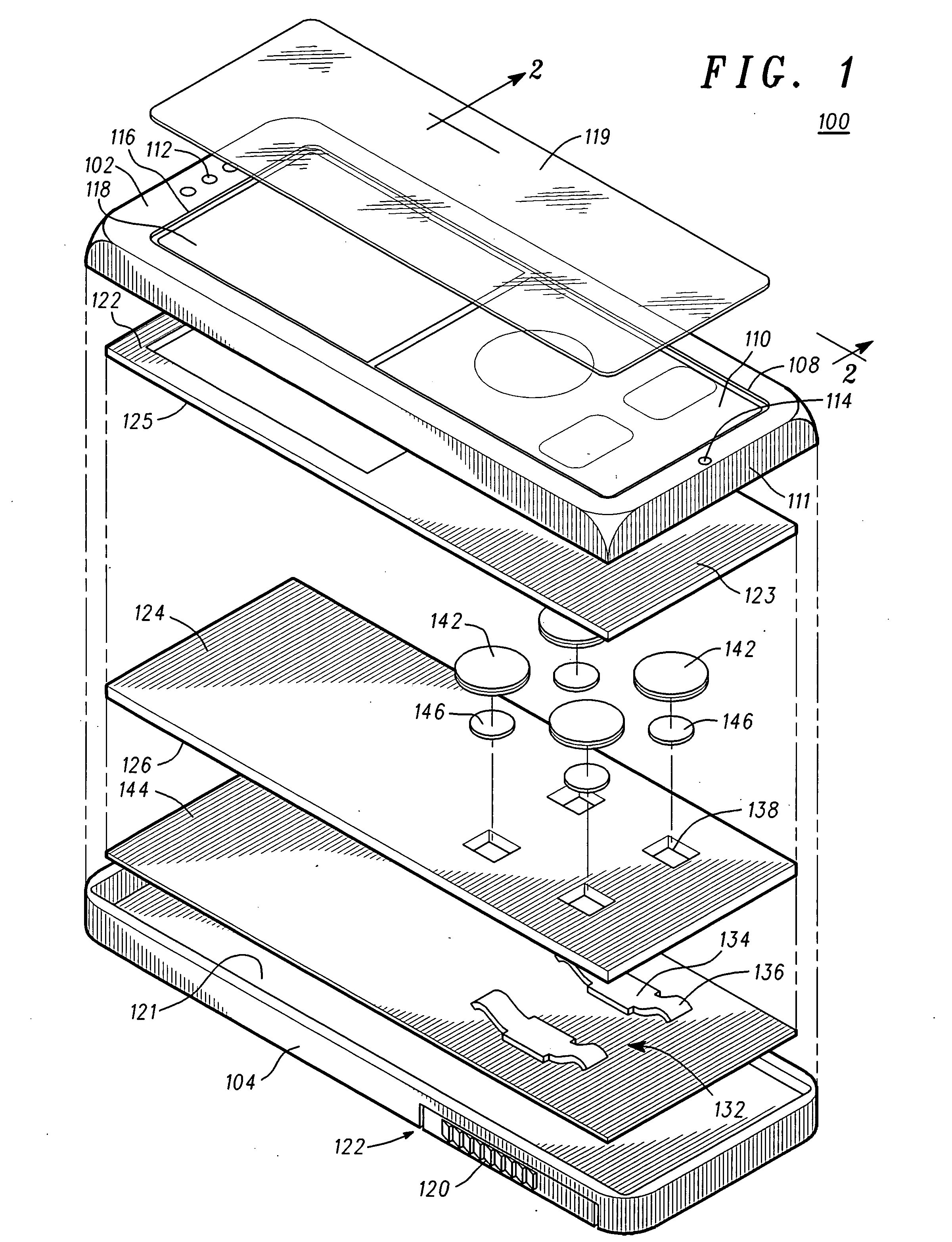
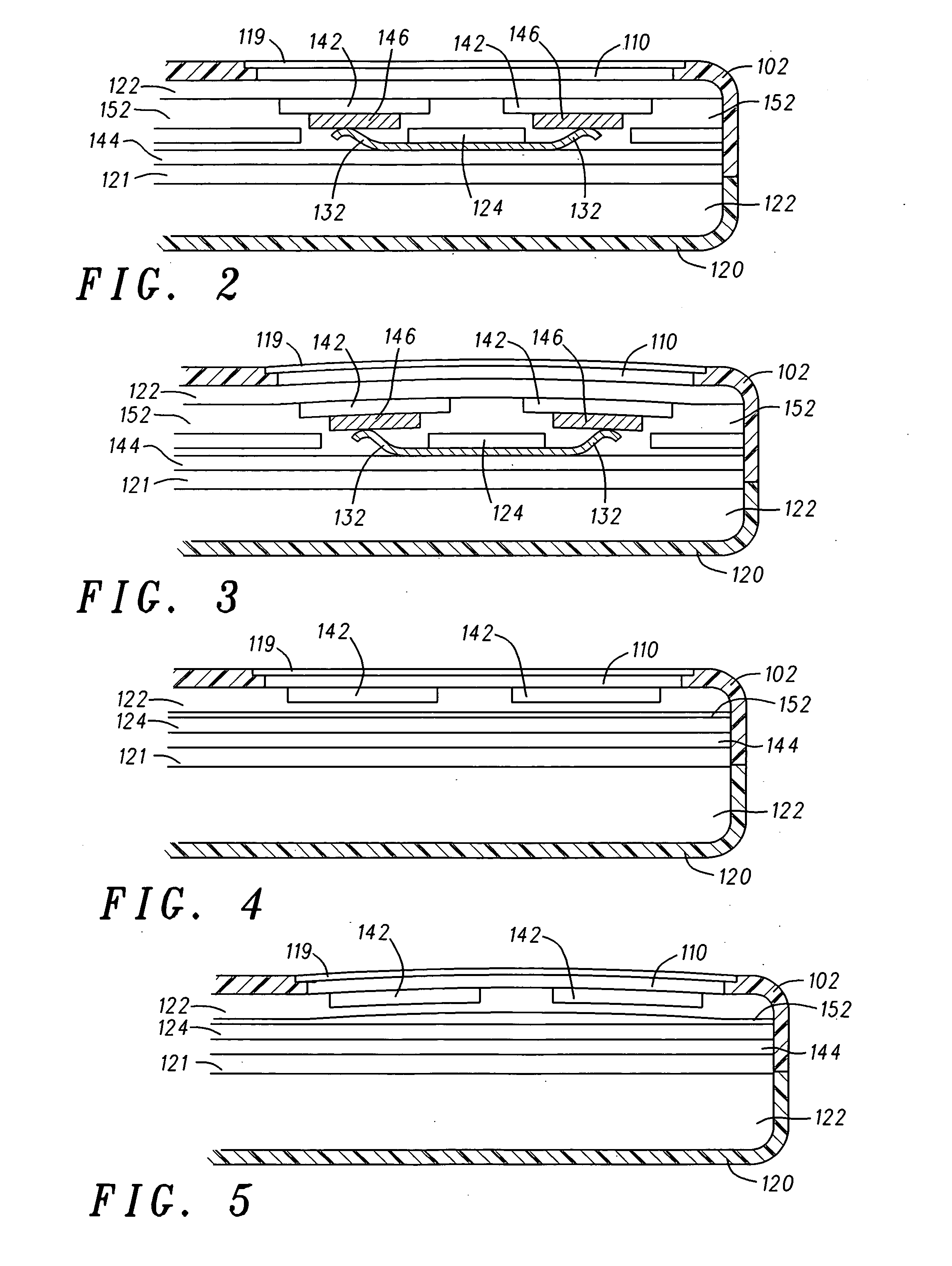
[0017]A piezoelectric ceramic element or multiple piezoelectric ceramic elements are directly bonded to the backbone structure of portable devices, for example the metal or plastic chassis of a cell phone. A chassis of a cell phone provides structural rigidity to the phone and serves as a structure plate for the attachment of most phone modules and components. The piezoelectric ceramic elements and an input device, e.g., a morphable user interface, are bonded to opposite sides of the chassis in one exemplary embodiment. Upon application of an electric field, the in-plane shrinkage or expansion of the piezoelectric elements causes localized f...


PUM


Abstract

An electronic device (100) provides tactile feedback provided by a low cost, thin piezoelectric actuator (142) giving tactile feedback emulating a click like feed. The electronic device (100) comprises a chassis plate (122) having a periphery secured to a housing (102, 104) and comprising a flexible material having a first planer side (123), and a second planer side (125) opposed to the first planer side (123). An input device (110) has a planer side (111) positioned adjacent to and in contact with to the first planer side (123) of the chassis (122) and extends through an opening (108) in the housing (102, 104). One or more piezoelectric actuators (142) are secured to the second planer side (125) and within the periphery of the chassis plate (122). Electronic circuitry (208) positioned within the housing (102, 104) drives the piezoelectric actuators (142) in response to the input device (110) being actuated. The input provided to the input device (110) is sensed by the electronic circuitry (208). The circuitry (208) provides a voltage waveform to activate the one or more piezoelectric actuators (142), which flexes the chassis plate (122) and the input device (110) to emulate the click like feed. A second exemplary embodiment positions the piezoelectric actuators (142) between the chassis plate (122) and the input device (110).

Description

FIELD OF THE INVENTION[0001]The present invention generally relates to electronic devices and more particularly to a portable communication device having tactile feedback.BACKGROUND OF THE INVENTION[0002]Morphable user interfaces are expected to be an important design consideration for the next generation of portable electronic devices. A morphable user interface is one that changes its appearance as the use of the device, e.g. phone, camera, music player, changes. Users will find the input interface simpler and more intuitive to use. However, the conventional means of providing tactile feedback when pressing a key, to a finger, for example, has been mechanical dome switches. Dome switches will not function well with morphable graphic user interfaces; therefore, haptics or active feedback becomes a critical enabler. While DC rotary or linear vibration motors could provide tactile feedback to a finger input with an optimized driving algorithm, the buzz-like vibration profile is very ...

Claims


Application Information

Patent Timeline
Patent Type & Authority Applications(United States)
IPC IPC(8): G09G5/00
CPCG06F3/016H10N30/20
Inventor KOCH, PAUL B.DAI, STEVE X.OLIVER, MANUEL
Owner MOTOROLA INC
Why Eureka
Try Eureka