Electric hand-held power tool

a power tool and electric technology, applied in the direction of portable power tools, cell components, coupling device connections, etc., can solve the problems of ineffective blocking means, and achieve the effect of ensuring dust resistance and increasing user safety

Inactive Publication Date: 2008-05-01
ROBERT BOSCH GMBH
View PDF2 Cites 1 Cited by
  • Summary
  • Abstract
  • Description
  • Claims
  • Application Information

AI Technical Summary

Benefits of technology

[0008]When the electric hand-held power tool is designed in accordance with the present invention, it has the advantage that, due to the inventive design of the locking device, an accidental actuation of one of the locking elements does not cause the energy accumulator module to be released and drop off of the machine housing. To remove the energy accumulator module, the energy accumulator module must be displaced relative to the machine housing, so that the blocking means become ineffective, and a locking element must be actuated manually while maintaining the displacement position. Only then may the energy accumulator module be pulled out of the guide, which is formed on the machine housing.
[0009]The inventive locking device greatly increases the user's safety when handling the electric hand-held power tool, and when working with and carrying the electric hand-held power tool. The inventive locking device is dust-proof, since the intermeshing locking elements need not necessarily be designed to be tight in the form-fit connection. Instead, an amount of play that guarantees dust-resistance may be maintained. The locking device may be realized using cost-favorable production methods, and it enables a modular design to be realized, so that different interfaces between the energy accumulator module and the machine housing may be accommodated when slightly modified designs of the locking device are used.

Problems solved by technology

To remove the energy accumulator module, the energy accumulator module must be displaced relative to the machine housing, so that the blocking means become ineffective, and a locking element must be actuated manually while maintaining the displacement position.

Method used


Image

  • Electric hand-held power tool
  • Electric hand-held power tool
  • Electric hand-held power tool

Examples


Embodiment Construction

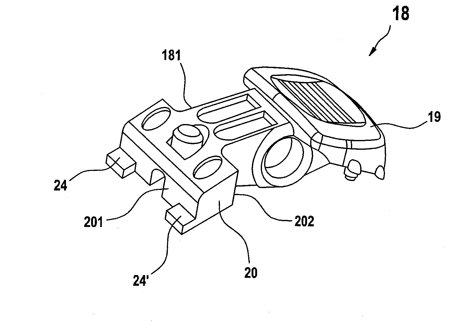
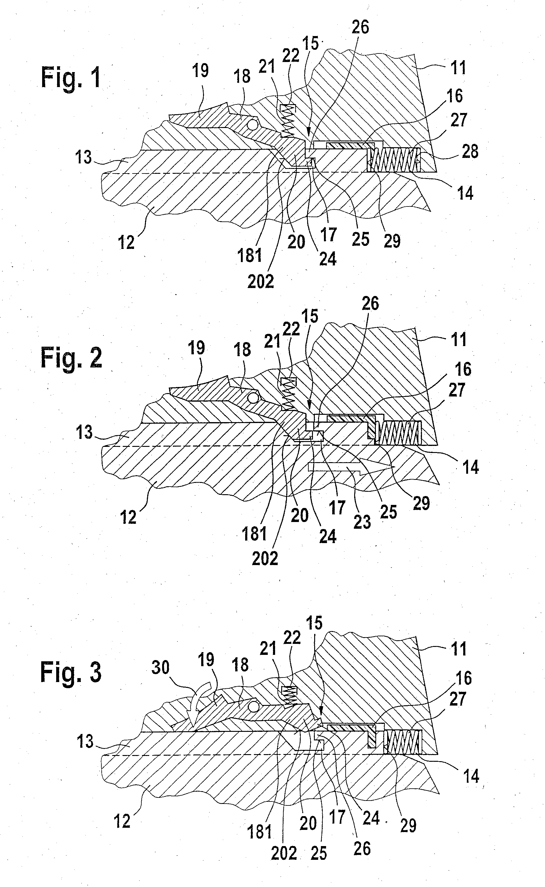
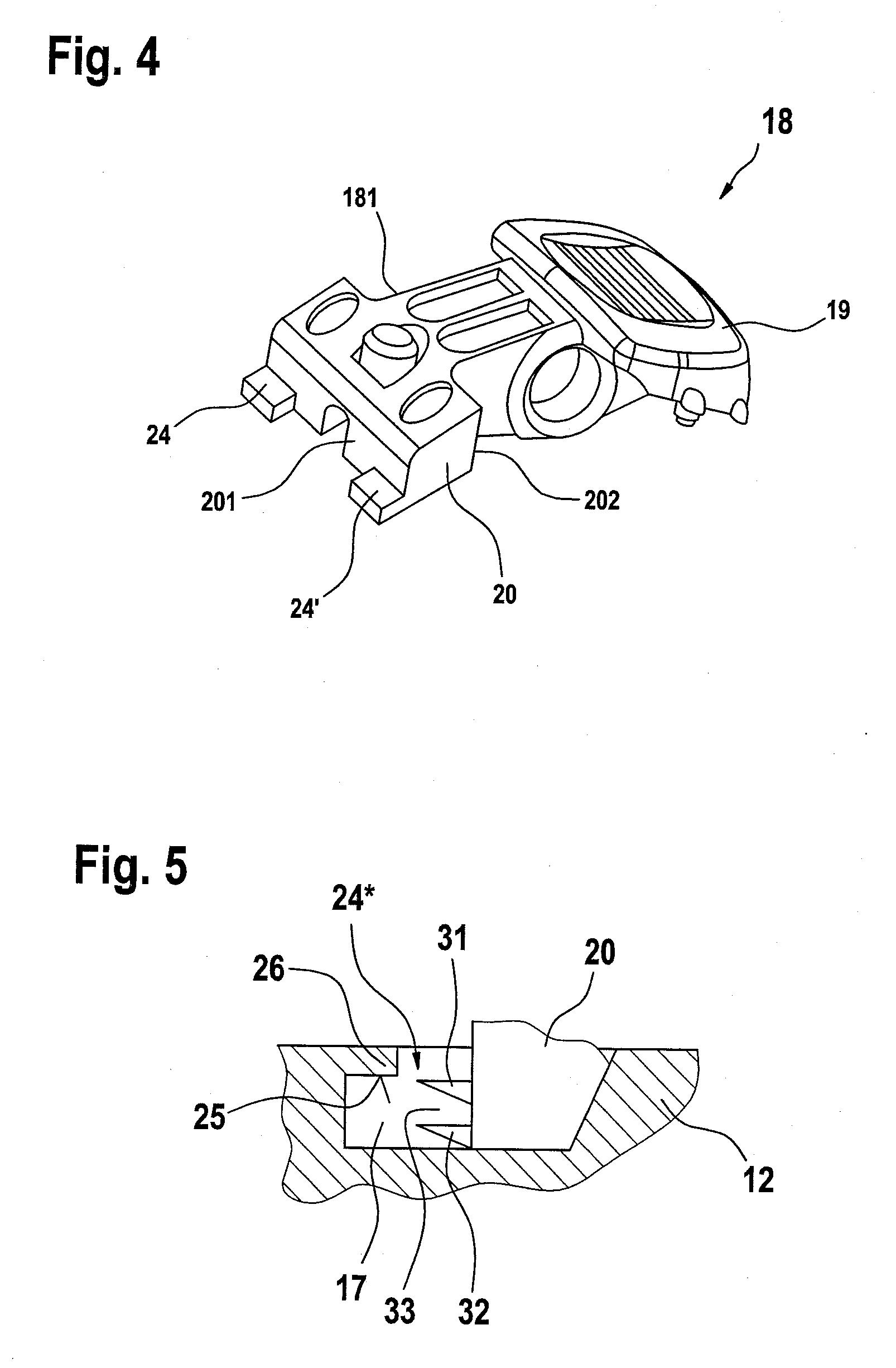
[0018]FIG. 1 shows a section of a machine housing 11 and an energy accumulator module 12 in the form of a rechargeable battery pack. The lower end of machine housing 11, which is designed as a handle, and the upper end of energy accumulator module 12, which may be placed on the handle of machine housing 11, are shown. A guide rail 13 is provided on the upper end of energy accumulator module 12, which may be slid into a guide 14 formed on the lower end of machine housing 11 for placement of energy accumulator module 12 on machine housing 11. Energy accumulator module 12, which has been placed on machine housing 11 in this manner, is locked in position reliably using a locking device 15. In the locked position shown in FIG. 1, the not-shown connection contacts of energy accumulator module 12 are contacted with not-shown connection contacts of the electric hand-held power tool, which are located on a contact holder 16 installed in machine housing 11.

[0019]Locking device 15 includes a l...


PUM


Abstract

An electric hand-held power tool has a machine housing, an energy accumulator module detachably connected therewith and slidable into and out of a guide formed on the machine housing, and a locking device acting between a machine housing and an energy accumulator module and including locking elements, which are located on the machine housing and the energy accumulator module and are engaged with each other in a locked position and may be disengaged manually. To prevent the locking device from becoming released when one of the locking elements designed as a release button is accidentally actuated, the locking device includes a blocking element active in the locked position of the locking elements and blocking manual actuation, wherein the blocking element can be deactivated by manually sliding energy accumulator module in the guide against a return force.

Description

CROSS-REFERENCE TO A RELATED APPLICATION[0001]The invention described and claimed hereinbelow is also described in German Patent Application DE 10 2006050816.5 filed on Oct. 27, 2006. This German Patent Application, whose subject matter is incorporated here by reference, provides the basis for a claim of priority of invention under 35 U.S.C. 119(a)-(d).BACKGROUND OF THE INVENTION[0002]The present invention is directed to an electric hand-held power tool.[0003]A known, cordless, hand-guided electric power tool (DE 10 2004 049 085 A1) includes a machine housing, on the lower end—designed as a handle—of which a battery pack or rechargeable battery pack is retained via a releasable locking device. The battery pack is slid via a guide rail into a guide formed in the exposed, lower end of the handle. The motion of inserting the guide rail into the guide is limited via interacting stop surfaces on the rear—as viewed in the direction of insertion—ends of the guide rail and the guide, which ...

Claims


Application Information

Patent Timeline
Patent Type & Authority Applications(United States)
IPC IPC(8): H01R4/28
CPCB25F5/02Y02E60/10H01M50/20
Inventor MATTHIAS, WOLFKRAUTER, JOCHEN
Owner ROBERT BOSCH GMBH
Why Eureka
Try Eureka