Collective Network For Computer Structures

a computer structure and network technology, applied in data switching networks, instruments, multi-processing architectures, etc., can solve the problems of insufficient processing power for software treatment to keep up with network bandwidth, inefficient computation, and inability to implement collective computation in the hardware of conventional networks, etc., to achieve efficient and reliable computation global reductions and limited resources

Inactive Publication Date: 2008-05-01
IBM CORP
View PDF14 Cites 36 Cited by
  • Summary
  • Abstract
  • Description
  • Claims
  • Application Information

AI Technical Summary

Benefits of technology

[0013]It is an object of the present invention to provide a system and method for interconnecting individual processing nodes of a computer structure so that they can efficiently and reliably compute global reductions, distribute data, synchronize, and share limited resources.

Problems solved by technology

One problem commonly faced on such massively parallel systems is the efficient computation of a collective arithmetic or logical operation involving many nodes.
Such a collective computation is not implemented in the hardware of conventional networks.
Furthermore, there may be insufficient processing power for the software treatment to keep up with the network bandwidth.
In addition, the topology of a conventional, multi-purpose network may reduce the efficiency of a collective computation, which is based on the longest path from any processing node involved in the computation to the processing node where the final result is produced.
A second problem commonly faced on massively-parallel systems is the efficient sharing of a limited number of external I / O connections by all of the processing nodes.
In either case, the network traffic caused by I / O can be disruptive because it is often asynchronous with respect to the application's communication.
A second drawback of sharing a single network between I / O and application communication is that the I / O bandwidth is limited to the bandwidth of the shared network.
A third drawback is that the topology of a shared network may restrict the freedom to use an optimal number of dedicated I / O processing nodes or locate them optimally.
The normal connectivity of high-speed networks such as the torus are simply not fully suited for this purpose because of longer latencies and because of the disruptive nature of I / O.

Method used


Image

  • Collective Network For Computer Structures
  • Collective Network For Computer Structures
  • Collective Network For Computer Structures

Examples


Embodiment Construction

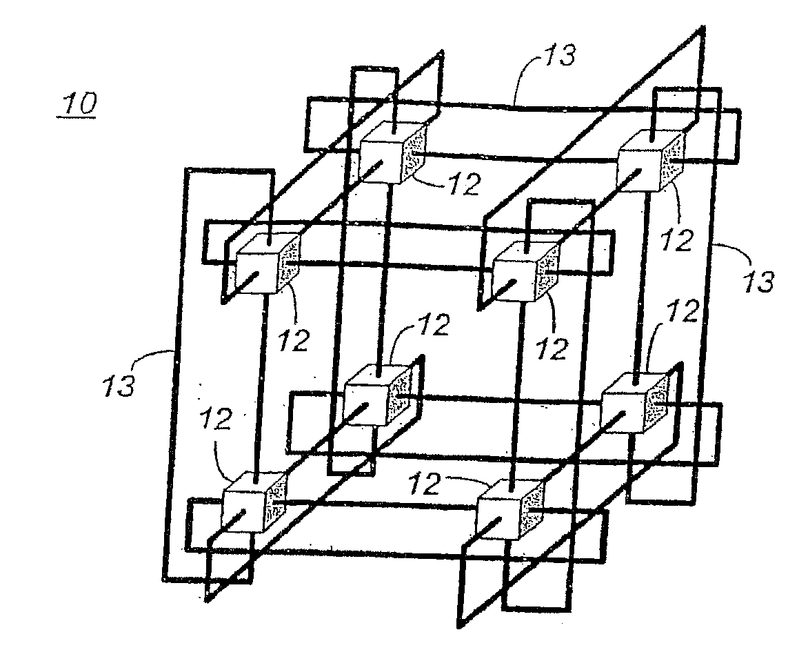
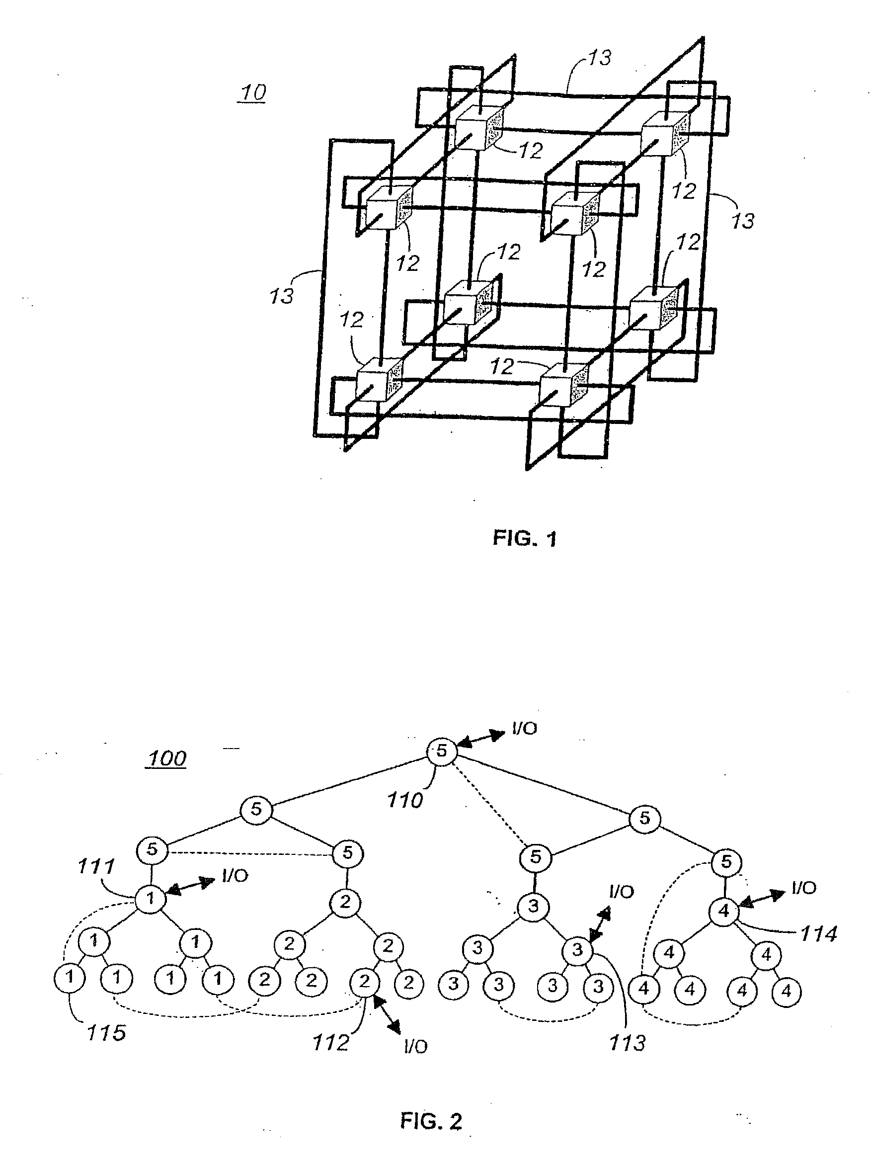
[0025]The present invention may be implemented in a computer structure such as described in herein-incorporated, commonly-owned, co-pending U.S. patent application Publication No. US 2004 / 0103218 A1, which describes a novel Massively Parallel Supercomputer architecture in the form of a three-dimensional torus designed to deliver processing power on the order of teraOPS (trillion floating-point operations per second) for a wide range of applications. The Massively Parallel supercomputer architecture, in the exemplary embodiment described, comprises 65,536 processing nodes organized as a 64×32×32 three-dimensional torus with each processing node connected to six (6) neighboring nodes. FIG. 1 shows such a torus consisting of eight (8) nodes 12, and it is clear to see how this interconnect scales by increasing the number of nodes 12 along all three dimensions. With current technology, this architecture can be leveraged to hundreds of teraOPS for applications that require significantly m...


PUM


Abstract

A system and method for enabling high-speed, low-latency global collective communications among interconnected processing nodes. The global collective network optimally enables collective reduction operations to be performed during parallel algorithm operations executing in a computer structure having a plurality of the interconnected processing nodes. Router devices ate included that interconnect the nodes of the network via links to facilitate performance of low-latency global processing operations at nodes of the virtual network and class structures. The global collective network may be configured to provide global barrier and interrupt functionality in asynchronous or synchronized manner. When implemented in a massively-parallel supercomputing structure, the global collective network is physically and logically partitionable according to needs of a processing algorithm.

Description

CROSS REFERENCE TO RELATED APPLICATIONS[0001]This application claims the benefit of commonly owned, copending U.S. Provisional Patent Application No. 60 / 589,076, filed Jul. 19, 2004, entitled “The Bluegene / L Tree Network,” the entire disclosure of which is expressly incorporated by reference herein as if fully set forth herein.[0002]This application is a continuation-in-part of commonly owned, copending U.S. patent application Ser. No. 10 / 469,000, filed Feb. 25, 2002, entitled “Global Tree Network For Computing Structure,” the entire disclosure of which is expressly incorporated by reference herein as if fully set forth herein.[0003]This patent application is additionally related to the following commonly-owned, co-pending (U.S. Patent Applications, the entire contents and disclosures of each of which is expressly incorporated by reference herein as if fully set forth herein:U.S. patent application Ser. No. 10 / 468,991, filed Feb. 25, 2002, for “Arithmetic Functions In Torus And Tree...

Claims


Application Information

Patent Timeline
Patent Type & Authority Applications(United States)
IPC IPC(8): G06F15/80G06F9/30
CPCG06F15/17381H04L12/4641H04L1/1845
Inventor BLUMRICH, MATTHIAS A.COTEUS, PAUL W.CHEN, DONGGARA, ALANGIAMPAPA, MARK E.HEIDELBERGER, PHILIPHOENICKE, DIRKTAKKEN, TODD E.STEINMACHER-BUROW, BURKHARD D.VRANAS, PAVLOS M.
Owner IBM CORP
Why Eureka
Try Eureka