Engine starting method and device

a technology of engine starting and starting mechanism, which is applied in the direction of engine starters, electric control, instruments, etc., can solve the problems of reducing the response of the engine, the inability to increase the motor torque by a reduction mechanism, and the use of a large, expensive motor

Active Publication Date: 2008-05-08
MAHLE INT GMBH
View PDF2 Cites 53 Cited by
  • Summary
  • Abstract
  • Description
  • Claims
  • Application Information

AI Technical Summary

Benefits of technology

[0028]According to the present invention, when the starter motor is reversely driven and the starter switch is turned off after the first fuel injection, the driving of the starter motor is not immediately stopped but the starter motor is con

Problems solved by technology

Particularly, when a rotor of the starter motor is directly connected to the crankshaft such as when a generator having a rotor directly connected to a crankshaft is used as a starter motor at the start of an engine, motor torque cannot be increased by a reduction mechanism, which requires use of a large expensive motor.
When the starter motor is used as the generator after the start of the engine, using a motor with high driving torque excessively increases inertia of the rotor because of a large mass thereof, thereby reducing response of the engine.
Startability and the response of the engine are in a trade-off relationship, and improvement in both thereof is difficult.
The engine is difficult to start under the extremely low temperature environments as described above because an increase in viscosity of engine oil or the like caused by a reduction in temperature suddenly increases torque (friction torque) applied to the crankshaft by sliding friction of a movable portion of the engine to excessively increase the maximum load torque (the sum of the compression torque and the friction torque) applied to the crankshaft in the compression stroke.
Specifically, under the extremely low temperature

Method used


Image

  • Engine starting method and device
  • Engine starting method and device
  • Engine starting method and device

Examples


Embodiment Construction

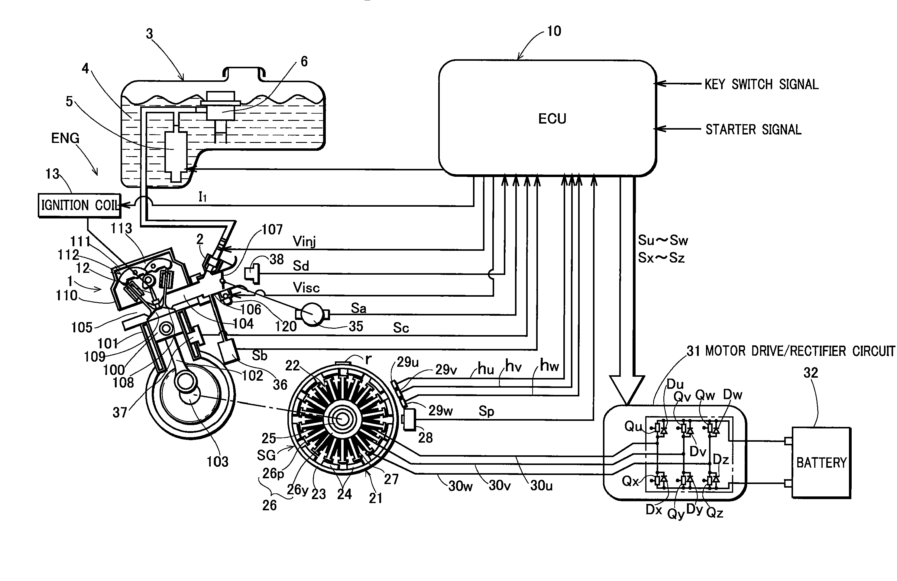
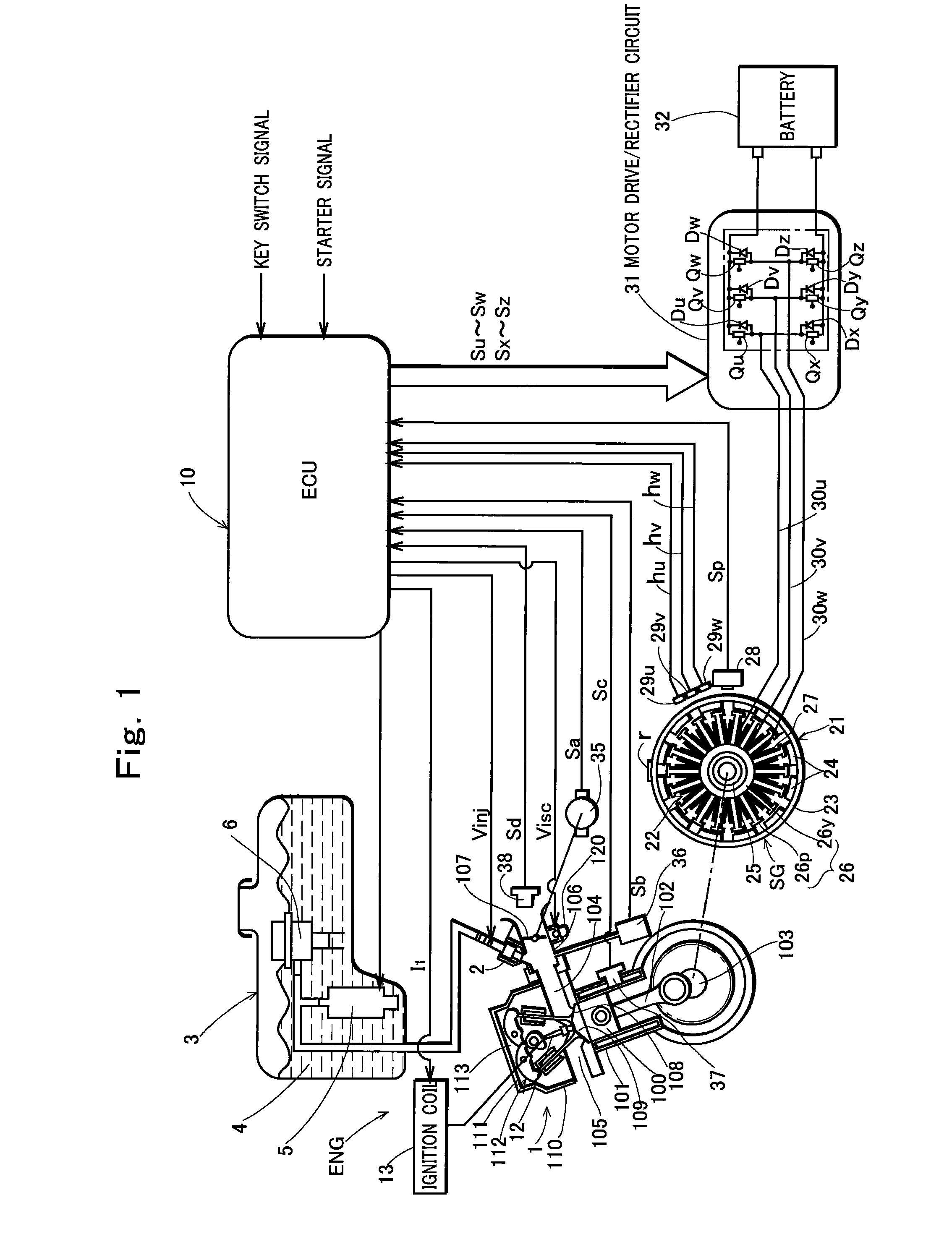
[0043]FIG. 1 shows a construction of an engine system comprising an engine starting device according to the present invention. In FIG. 1, ENG denotes a parallel two cylinder four cycle engine, and combustion cycles of a first cylinder and a second cylinder of the engine have a phase difference of 360°. A reference numeral 1 denotes an engine body, which comprises two cylinders 101 (the first cylinder only is shown) having a piston 100 therein, and a crankshaft 103 connected to the piston 100 in the cylinder via a connecting rod 102.

[0044]The starting device according to the present invention may be applied to the case where one common intake pipe is provided for a plurality of cylinders, but in the embodiment, an intake pipe 104 is provided for each cylinder of the engine. The engine ENG also comprises a fuel injection device that injects fuel for generating an air / fuel mixture to be supplied into the cylinder 101 through an intake pipe 106, an ignition device that ignites the air / f...


PUM


Abstract

An engine starting method for starting an engine by causing first fuel injection when a crankshaft is reversely rotated by a predetermined angle at the start, and then rotating the crankshaft forward to perform first ignition, the method comprising the steps of immediately stopping driving of a starter motor when a starter switch is turned off before the first fuel injection at the start; and continuously driving the starter motor forward until a cylinder into which an air/fuel mixture is supplied by the first fuel injection performs at least one exhaust stroke and then stopping the driving of the starter motor when the starter switch is turned off after the first fuel injection at the start.

Description

TECHNICAL FIELD OF THE INVENTION[0001]The present invention relates to an engine starting method for starting an engine comprising a starter motor, and an engine starting device used for implementing the method.PRIOR ART OF THE INVENTION[0002]Generally, when an engine is stopped, a compression load in a compression stroke of the engine acts as a brake in the process of inertial rotation of a crankshaft, the rotation once stops in the process of a piston in any of cylinders moving up toward a top dead center of the compression stroke, and then the piston is pushed back and stopped near a bottom dead center in many cases. Thus, in starting the engine, the crankshaft is rotated from the state where the piston in any of the cylinders is positioned near the bottom dead center of the compression stroke.[0003]When the crankshaft is rotated forward for starting the engine in this position, the compression load of the compression stroke is applied to the crankshaft immediately after the star...

Claims


Application Information

Patent Timeline
IPC IPC(8): F02N11/00F02D41/06
CPCF02D41/062F02N11/08F02N2019/007F02N19/005F02N99/004F02N11/0848F02N11/0803
Inventor KISHIBATA, KAZUYOSHIKINOSHITA, TOMOHIRO
Owner MAHLE INT GMBH
Why Eureka
Try Eureka