Time Segmentation of Frequencies in Controlled Source Electromagnetic (CSEM) Applications

a technology of controlled source electromagnetic and time segmentation, applied in the field of hydrocarbon exploration, can solve the problems of time-consuming and uneconomic multiple passes over the subsurface formation, large reduction of energy generated at any particular frequency using this method, and low noise ratio

Inactive Publication Date: 2008-05-08
WESTERNGECO LLC
View PDF5 Cites 19 Cited by
  • Summary
  • Abstract
  • Description
  • Claims
  • Application Information

AI Technical Summary

Benefits of technology

[0013]In another aspect, the invention relates to an electromagnetic survey system that includes one or more receivers positioned on a seafloor, an electromagnetic transmitter that includes a first electrode electrically connected to the source, and a second electrode electrically connected to the source. The source may be configured to transmit continuously a signal at a first fundamental frequency at full power for a first period of time within a single window of time causing electromagnetic energy to propagate in the subsurface formations, and transmit continuously the signal at a second fundamental frequency at full power for a second period of time within the single window of time causing electromagnetic energy to propagate in the subsurface formations. The system may also include a computer containing executable code such that when executed, causes the computer to analyze data from the receivers to determine a characteristic of a sub-surface formation.

Problems solved by technology

However, having to make multiple passes over the subsurface formations is time consuming and uneconomic.
However, the energy generated at any particular frequency is greatly reduced using this method.
By generating less power at any particular frequency, the signal-to-noise ratio is lower thereby making it more difficult to accurately measure the resistivity in the subsurface formations.
Hence, this alternative method also has problems with having a low signal-to-noise ratio thereby making it more difficult to accurately measure the resistivity in the subsurface formations.

Method used


Image

  • Time Segmentation of Frequencies in Controlled Source Electromagnetic (CSEM) Applications
  • Time Segmentation of Frequencies in Controlled Source Electromagnetic (CSEM) Applications
  • Time Segmentation of Frequencies in Controlled Source Electromagnetic (CSEM) Applications

Examples


Embodiment Construction

[0020]Refer now to the drawings wherein depicted elements are not necessarily shown to scale and wherein like or similar elements are designated by the same reference numeral through the several views.

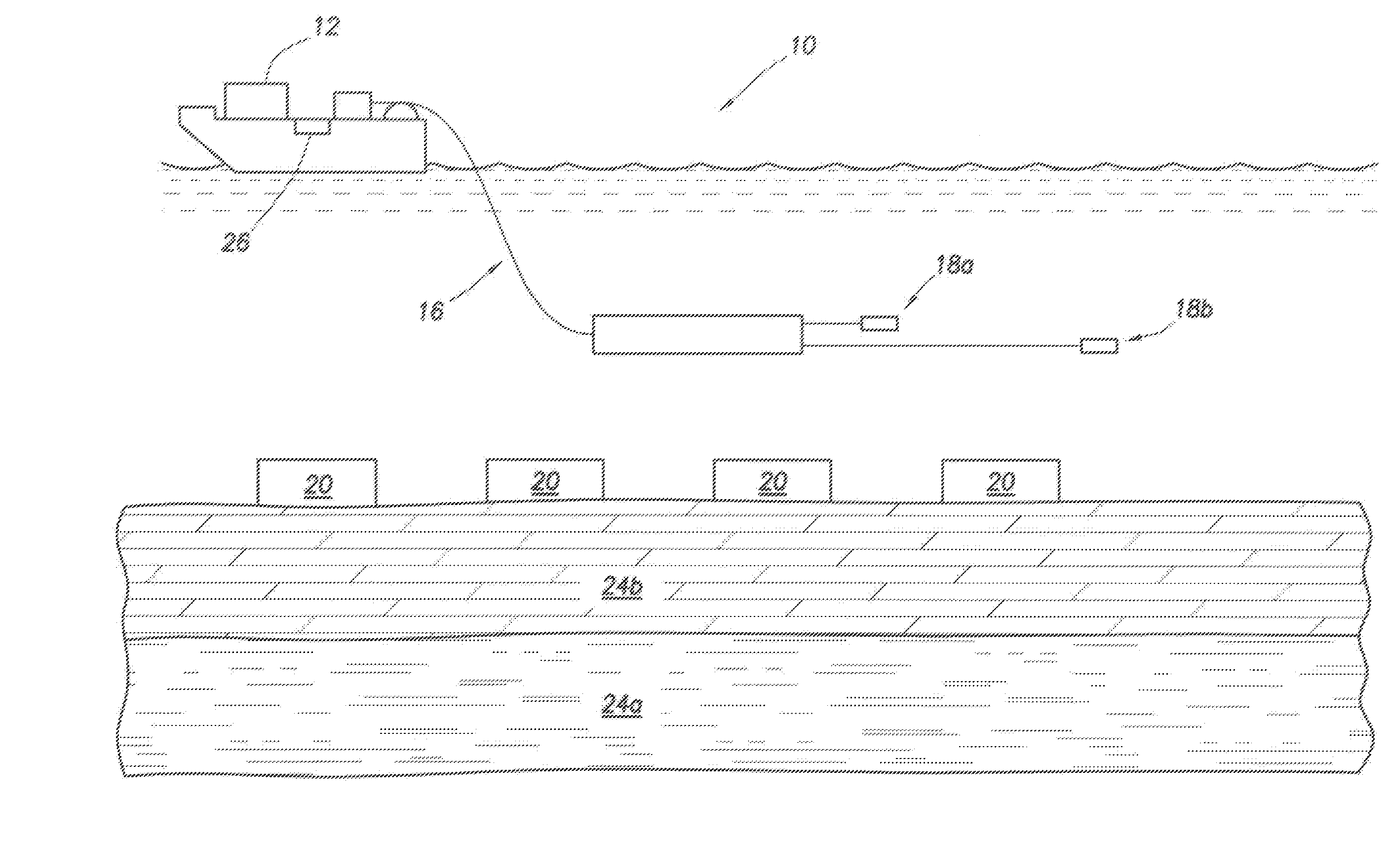
[0021]FIG. 1 illustrates a CSEM system 10 for measuring the resistivity in subsurface formations 24 in accordance with an embodiment of the present invention. System 10 includes a vessel 12 towing a transmitter or source 14 via a cable 16. System 10 includes receivers 20 positioned on the sea floor 22 above subsurface formations 24. For exemplary purposes, formation 24b is a shale formation and formation 24a is an oil-sand.

[0022]Transmitter 14 includes electrodes 18a, 18b. Transmitter 14 is configured to generate a time-varying current. Electrodes 18a, 18b are coupled electrically via the sea water, which acts as a conductor thereby forming a circuit carrying a time-varying current generated by transmitter 14. Transmitter 14 is configured to generate an output current at various freque...


PUM


Abstract

A method for measuring a resistivity of a subsurface formation that includes transmitting continuously a signal at a first fundamental frequency at full power for a first period of time within a single window of time causing electromagnetic energy to propagate in the subsurface formations, transmitting continuously the signal at a second fundamental frequency at full power for a second period of time within the single window of time causing electromagnetic energy to propagate in the subsurface formations, measuring variations in the electromagnetic energy propagated through the subsurface formations at receivers at the first and the second fundamental frequencies, and determining the resistivity of the subsurface formations using the measurements of the variations in electromagnetic energy at the receivers.

Description

FIELD OF THE INVENTION[0001]The present invention relates to the field of hydrocarbon exploration, and more particularly to transmitting each different frequency used in controlled source electromagnetic applications within a time window at full power.BACKGROUND[0002]Subsurface porous rocks are saturated with fluids. The fluids may be water (salt water or fresh water) or hydrocarbons (gas or oil). The resistivity of a formation may depend heavily on the fluid that is contained within the formation. For example, formations containing hydrocarbons or fresh water tend to be much more resistive that formations that contain salt water. As a result, the resistivity of subsurface formations (e.g., porous rocks) may be measured to determine if the formation is likely to contain hydrocarbons.[0003]The resistivity of subsurface formations may be measured using various methods including a method commonly referred to as controlled source electromagnetics (CSEM). CSEM typically uses a finite siz...

Claims


Application Information

Patent Timeline
Patent Type & Authority Applications(United States)
IPC IPC(8): G01V3/00
CPCG01V3/12G01V3/083
Inventor CAMPBELL, TRACY
Owner WESTERNGECO LLC
Why Eureka
Try Eureka