Arrangement for monitoring the energy radiated by an EUV radiation source

a technology of radiation source and arrangement, which is applied in the direction of optical radiation measurement, printers, instruments, etc., can solve the problems of limited reflectivity of collector and mirror, optical loss, and inability to achieve the desired effect of mirror optics,

Inactive Publication Date: 2005-05-17
USHIO DENKI KK
View PDF7 Cites 24 Cited by
  • Summary
  • Abstract
  • Description
  • Claims
  • Application Information

AI Technical Summary

Benefits of technology

[0015]It is the primary object of the invention to find a novel possibility for detecting variations in the radiation emitted by EUV sources which allows fluctuations in pulse energy as well as spatial fluctuations acting in the illumination beam path to be detected.

Problems solved by technology

Optical losses occur due to the limited reflectivity of the collector and mirrors and due to so-called geometric losses.
Therefore, mirror optics which couple out light are not desired in the illumination beam path for coupling out at least a part of the radiation to an energy detector.
For this reason, previously known EUV radiation sources are usually operated without regulation because measurements impair the energy flux during operation.

Method used


Image

  • Arrangement for monitoring the energy radiated by an EUV radiation source
  • Arrangement for monitoring the energy radiated by an EUV radiation source
  • Arrangement for monitoring the energy radiated by an EUV radiation source

Examples


Embodiment Construction

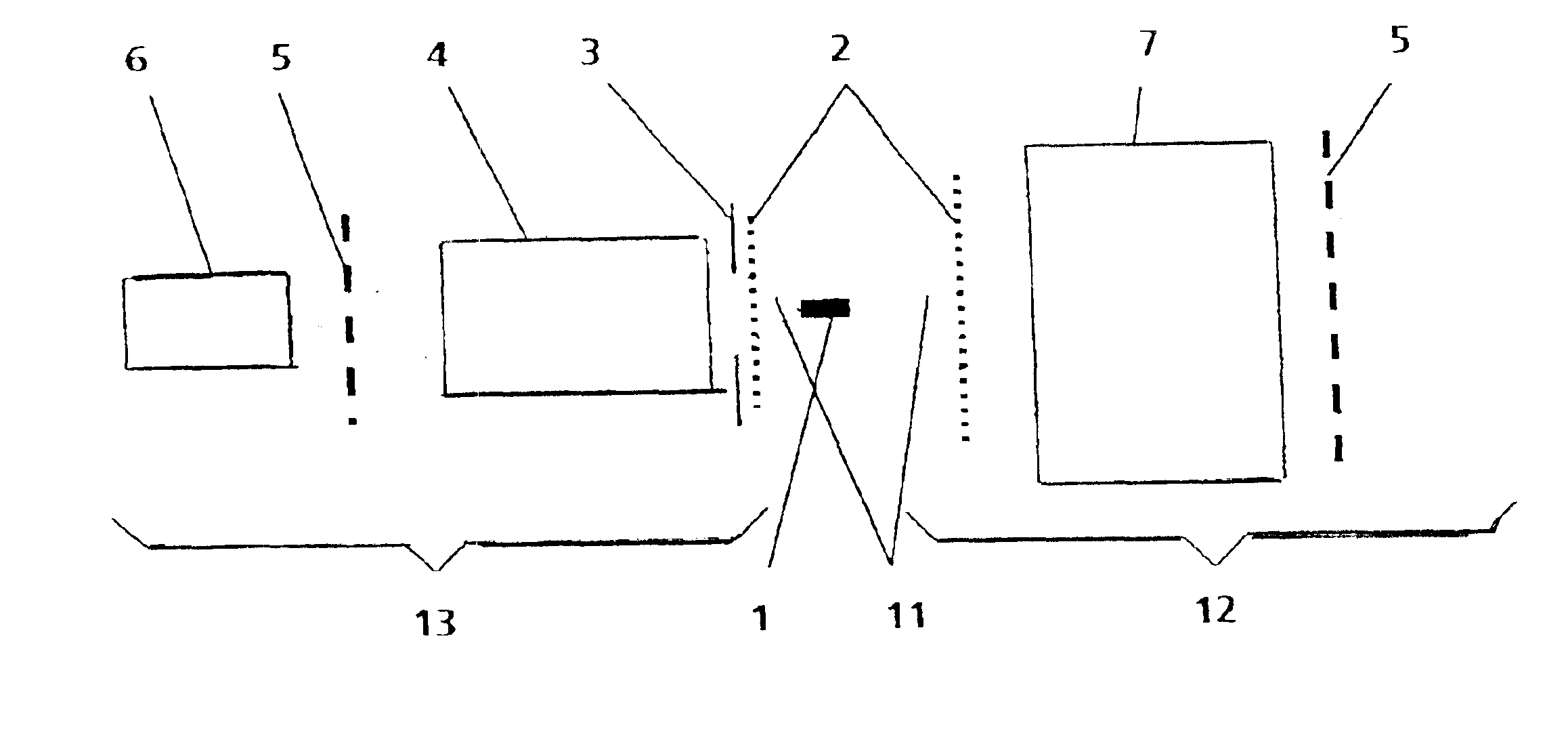
[0032]In a basic arrangement of an EUV source in which a hot plasma column 1 is generated in an optional manner, the invention comprises, on the one hand, an illumination beam path 12 with collector optics 7 collecting EUV radiation emitted from the plasma column 1 and transmitting it for transfer to a location of use (e.g., a scanner for semiconductor lithography, not shown) and, on the other hand, a detection beam path 13 with an energy monitoring unit 6 to which the emitted EUV radiation 11 is directed by reflection optics 4.

[0033]FIG. 1 shows a simplified overview of the invention, wherein the plasma column 1 is generated, for example, by a gas-discharge pumped EUV source, e.g., with Z-pinch (not shown). However, the plasma column 1 can also be generated by laser radiation.

[0034]As is illustrated in FIG. 1, the light path to the scanner (referred to above as illumination beam path 12) is opened, according to the invention, to all elements for monitoring the emitted EUV radiation...


PUM


Abstract

The invention is directed to an arrangement for monitoring the energy radiated by an EUV radiation source with respect to energy variations acting in an illumination beam path, wherein the radiation source has a plasma column emitting extreme ultraviolet radiation. The arrangement includes an energy monitoring unit, and a detection beam path. The detection beam path is separate from the illumination beam path and is arranged with the energy monitoring unit for detecting pulse energy, so that the illumination beam path is not impaired by the energy measurement. The detection beam path is matched to the illumination beam path with respect to bundle extension and optical losses.

Description

CROSS-REFERENCE TO RELATED APPLICATIONS[0001]This application claims priority of German Application No. 102 04 994.7, filed Feb. 5, 2002, the complete disclosure of which is hereby incorporated by reference.BACKGROUND OF THE INVENTION[0002]a) Field of the Invention[0003]The invention is directed to an arrangement for monitoring the energy radiated by an EUV radiation source with respect to the energy variations taking place in an illumination beam path, particularly for controlling dose stability in EUV lithography for chip fabrication in semiconductor technology.[0004]b) Description of the Prior Art[0005]In addition to special lamps, narrow-band excimer lasers with wavelengths of 248 nm and 193 nm are currently used as radiation sources for producing microchips. Scanners based on F2 lasers (157 nm) are in development at this time.[0006]In all photolithography processes, a mask (containing the structure to be imaged) is imaged on a wafer (semiconductor disk) in the scanner in a redu...

Claims


Application Information

Patent Timeline
Patent Type & Authority Patents(United States)
IPC IPC(8): G01J1/42
CPCG01J1/429G21K1/10G03F7/7085G03F7/70558
Inventor KLEINSCHMIDT, JUERGENSTAMM, UWE
Owner USHIO DENKI KK
Why Eureka
Try Eureka