Robot apparatus, and load absorbing apparatus and method

a technology of robots and actuators, applied in the direction of electric controllers, program control, instruments, etc., can solve the problems of two-leg type, easy to be damaged by other members, and the posture and walking of robots are difficult to control, so as to prevent the spread of damage to other members, reduce the overload of motors, and prevent the effect of member breakag

Inactive Publication Date: 2005-07-28
SONY CORP
View PDF5 Cites 22 Cited by
  • Summary
  • Abstract
  • Description
  • Claims
  • Application Information

AI Technical Summary

Benefits of technology

[0021] An additional object of this invention is to provide an advanced robot apparatus, and a load absorbing apparatus and method, which are capable of appropriately detecting overload which may break a motor and deform the body, and reducing the overload in the motor.
[0044] Still further, this invention can provide an advanced robot apparatus, and a load absorbing apparatus and method, which are capable of appropriately preventing breakage of members and the body due to overload applied to motors having a single or multiple axes in a multi-joint type robot comprising a plurality of actuator motors.

Problems solved by technology

As compared with crawler, four-leg, or six-leg type robots, two-leg type robot is unstable when moving, and its posture and walking are hard to be controlled.
On the other hand, overload may be applied to its joint actuators when it falls down, bumps against something, and gets something into its body.
Such overload may cause fatal damage, for example, breakage or plastic deformation of its body.
This conventional torque limiter 130, however, has a problem in that static friction coefficients between the ring 131 and the first and second friction plates 132A and 132B vary easily and widely, so that it is difficult to determine an allowable margin at the time of designing a robot.
Furthermore, since the conventional torque limiter 130 is constructed mechanically as described above, it is hard to construct a smaller and lighter torque limiter and to therefore realize a smaller and lighter robot which contains motors.

Method used


Image

  • Robot apparatus, and load absorbing apparatus and method
  • Robot apparatus, and load absorbing apparatus and method
  • Robot apparatus, and load absorbing apparatus and method

Examples


Embodiment Construction

[0075] Preferred embodiments of this invention will be described with reference to the accompanying drawings:

(1) Construction of Robot of This Embodiment

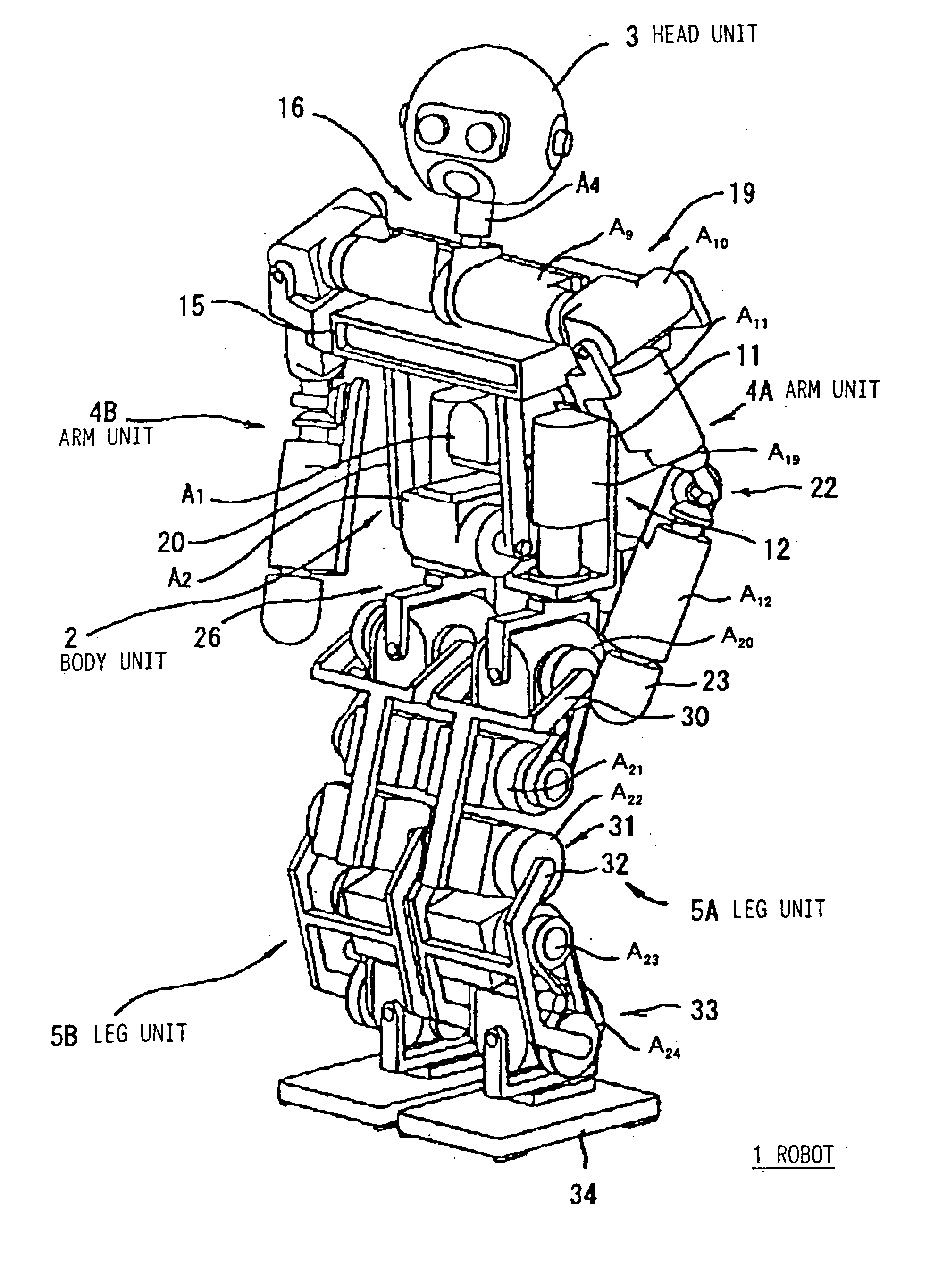
[0076]FIG. 3 and FIG. 4 show an entire construction of a two-legged walking robot according to one embodiment of the present invention. In addition, FIG. 5 schematically shows a structure of a degree of freedom in the robot. Reference numeral 1 shows a two-leg walking type robot as a whole, in which a head unit 3 is placed on a body unit 2, arm units 4A, 4B having the same construction are provided at upper left and right parts of the body unit 2, respectively, and leg units 5A, 5B having the same construction are provided at lower left and right parts of the body unit 2, respectively.

[0077] The body unit 2 is constructed of an upper body frame 10 and a waist base 11 forming a lower body both of which are connected to each other via a waist joint mechanism 12. By driving each of actuators A1, A2 of the waist joint mechanism 12 f...


PUM


Abstract

To appropriately detect overload which may break a motor or deform a body and reduce the overload in the motor. The DC component of a load torque is derived from the sum of absolute values of a torque applied to a link connected to the output shaft of a motor and the generated torque of the motor, and it is determined that overload has been applied when the DC component exceeds a first threshold value for a prescribed period of time or longer. In addition, considering such a characteristic that the variation of energy applied to the output shaft of a motor is in proportion to a product of the torque and the angular velocity of the motor, the AC component of the load torque is detected based on the variation of energy, and it is predicted that overload will be applied when the AC component exceeds a second threshold value.

Description

CROSS REFERENCE TO RELATED APPLICATIONS [0001] This application is a continuation of and claims priority under 35 U.S.C. § 120 to co-pending U.S. application Ser. No. 10 / 731,145, filed Dec. 10, 2003 and is also based upon and claims priority under 35 U.S.C. § 119 from Japanese Patent Application Nos. 2002-367353, filed Dec. 18, 2002 and 2003-367477, filed Oct. 28, 2003, the entire contents of which are incorporated herein by reference.BACKGROUND OF THE INVENTION [0002] 1. Field of the Invention [0003] This invention relates to a robot apparatus, and a load absorbing apparatus and method for absorbing load applied to a motor, and specifically, to a robot apparatus, and a load absorbing apparatus and method for motors which are used as actuators for joint motion of a multi-joint type robot. [0004] For more detail, this invention relates to a robot apparatus, and a load absorbing apparatus and method for appropriately detecting and controlling overload which is applied to a motor and m...

Claims


Application Information

Patent Timeline
Patent Type & Authority Applications(United States)
IPC IPC(8): B25J19/06B25J5/00B25J9/16F16D7/00G05B11/01H02P7/00H02P29/02
CPCG05B2219/37342B25J9/1633G05B2219/42289
Inventor IRIBE, MASATSUGUYAMANAKA, HAJIME
Owner SONY CORP
Why Eureka
Try Eureka