Multiple lens imaging apparatuses, and methods and programs for setting exposure of multiple lens imaging apparatuses

a technology of multiple lens imaging and exposure, which is applied in the direction of exposure control, instruments, television systems, etc., can solve the problems of complex configuration of a corresponding multiple lens imaging apparatus, large apparatus size, and substantial discomfort of viewing stereo images or panoramic images generated from images, so as to reduce the brightness of subjects photographed by the main imaging unit and the sub-imaging unit, the effect of easy setting of exposur

Active Publication Date: 2008-05-08
FUJIFILM CORP
View PDF9 Cites 27 Cited by
  • Summary
  • Abstract
  • Description
  • Claims
  • Application Information

AI Technical Summary

Benefits of technology

[0032]In this manner, a difference in brightness of a subject photographed by the main imaging unit and the sub-imaging unit can be reduced. Therefore, the exposure can be set more easily.

Problems solved by technology

Therefore, an amount of light is different between images from the respective imaging units, and a stereo image or a panoramic image generated from the images is substantially uncomfortable to view.
Therefore, the configuration of a corresponding multiple lens imaging apparatus becomes complex, and the apparatus becomes larger in size.
However, the calculated exposure value is not necessarily appropriate for the other imaging unit.

Method used


Image

  • Multiple lens imaging apparatuses, and methods and programs for setting exposure of multiple lens imaging apparatuses
  • Multiple lens imaging apparatuses, and methods and programs for setting exposure of multiple lens imaging apparatuses
  • Multiple lens imaging apparatuses, and methods and programs for setting exposure of multiple lens imaging apparatuses

Examples


first embodiment

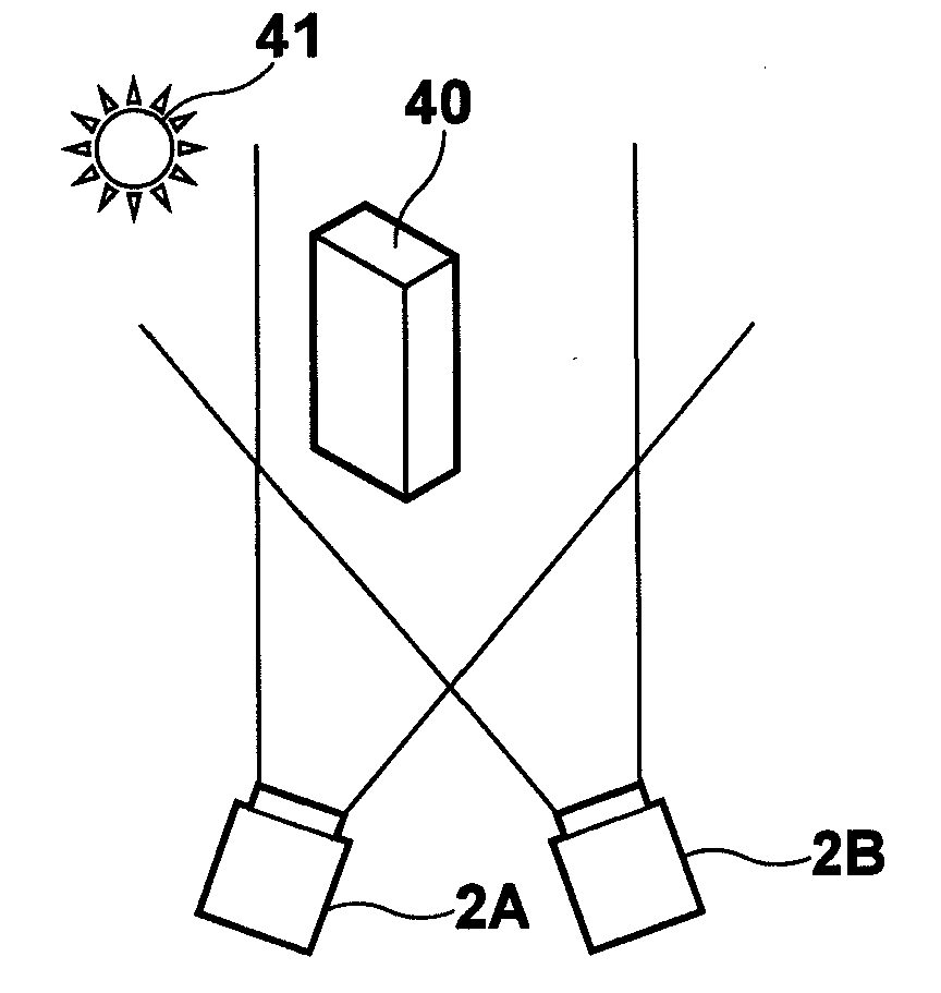
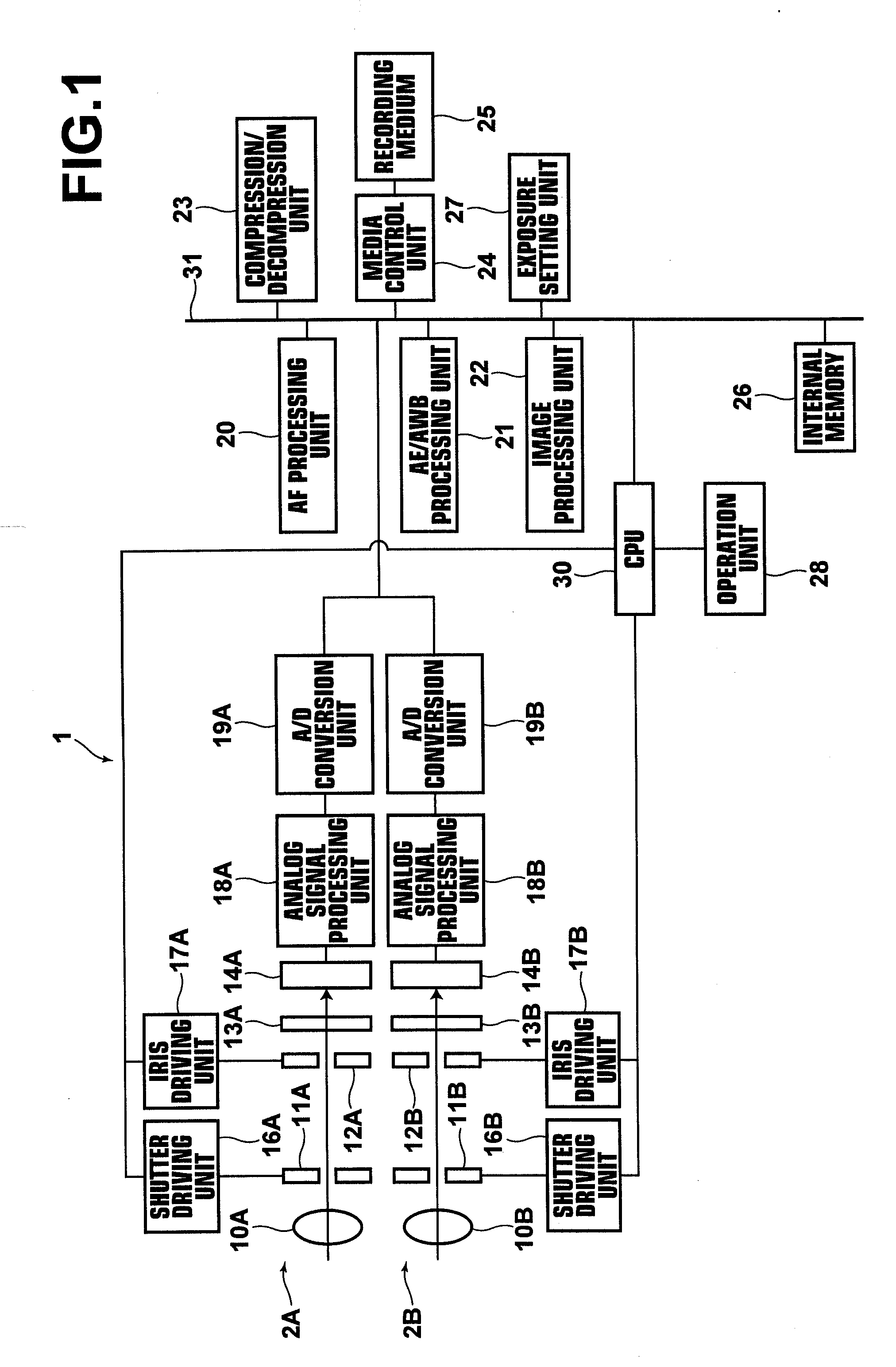
[0067]Hereinafter, embodiments of the present invention will be described with reference to the accompanying drawings. FIG. 1 shows the configuration of a multiple lens imaging apparatus of the present invention. A multiple lens imaging apparatus 1 shown in FIG. 1 is used for generating a stereo image after obtaining two images having a parallax by photography of the same subject with two spaced imaging units 2A and 2B. Alternatively, the multiple lens imaging apparatus may be used for generating a panoramic image from images obtained by the two imaging units 2A and 2B located in parallel to each other. The images obtained by the two imaging units 2A and 2B may be still images or moving images. In the embodiments described below, the images refer to still images.

[0068]The imaging units 2A and 2B comprise lenses 10A and 10B, shutters 11A and 11B, irises 12A and 12B, optical filters 13A and 13B, CCDs 14A and 14B, shutter driving units 16A and 16B, iris driving units 17A and 17B, analo...

second embodiment

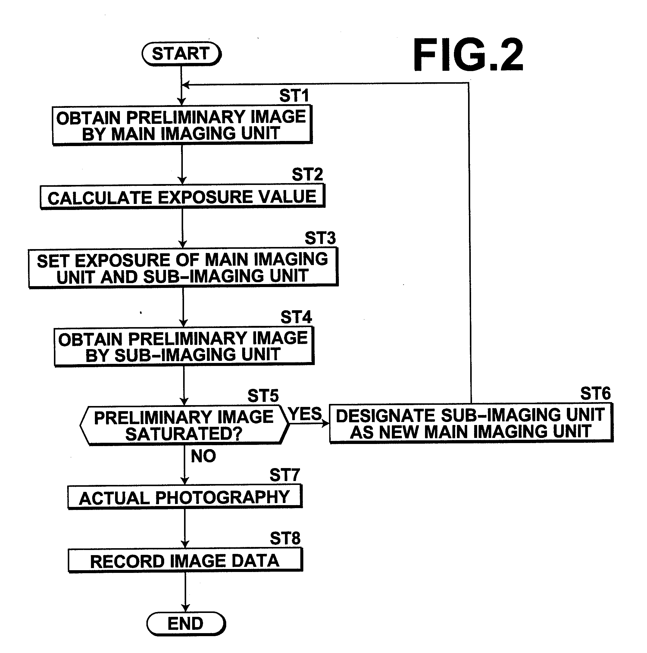
[0096]FIG. 7 is a flow chart showing exposure setting processing in the When a photographer instructs the start of photography by using the operation unit 28, the CPU 30 starts the processing. The exposure setting unit 27 instructs the main imaging unit 2A to obtain the preliminary image, and the main imaging unit 2A obtains the preliminary image (Step ST11). The AE / AWB processing unit 21 carries out the AE processing by using the preliminary image, and calculates the exposure value (Step ST12). The exposure setting unit 27 sets the exposure of the main imaging unit 2A and the sub-imaging units 2B and 2C, based on the calculated exposure value (Step ST13).

[0097]The exposure setting unit 27 then instructs the sub-imaging units 2B and 2C whose exposure has been set to obtain the preliminary images, and the sub-imaging units 2B and 2C obtain the preliminary images (Step ST14). The exposure setting unit 27 judges whether the preliminary images are saturated (Step ST15).

[0098]If the res...

third embodiment

[0103]FIG. 8 is a flow chart showing exposure setting processing in the When a photographer instructs the start of photography by using the operation unit 28, the CPU 30 starts the processing. The exposure setting unit 27 instructs the main imaging unit 2A to obtain the preliminary image, and the main imaging unit 2A obtains the preliminary image (Step ST31). The AE / AWB processing unit 21 carries out the AE processing by using the preliminary image, and calculates the exposure value (Step ST32). The exposure setting unit 27 sets the exposure of the main imaging unit 2A and the sub-imaging units 2B and 2C, based on the calculated exposure value (Step ST33).

[0104]The exposure setting unit 27 then instructs the sub-imaging units 2B and 2C whose exposure has been set to obtain the preliminary images, and the sub-imaging units 2B and 2C obtain the preliminary images (Step ST34). The exposure setting unit 27 judges whether the preliminary images are saturated (Step ST35).

[0105]If the res...


PUM


Abstract

When an exposure value calculated according to a result of photometric measurement for predetermined main imaging units among a plurality of imaging units is used for setting exposure of the main imaging units and sub-imaging units other than the main imaging units, judgment is carried out as to whether an image or images obtained in photography with the sub-imaging units by setting the exposure thereof according to the exposure value is/are saturated. In the case where a result of the judgment is affirmative, any one of the sub-imaging units having obtained the saturated image or images is designated as new main imaging units. The exposure value is calculated newly, and the exposure is set for the new main imaging units and for new sub-imaging units other than the new main imaging units.

Description

BACKGROUND OF THE INVENTION[0001]1. Field of the Invention[0002]The present invention relates to multiple lens imaging apparatuses each having a plurality of imaging units and to methods for setting exposure of the multiple lens imaging apparatuses. The present invention also relates to programs that cause a computer to execute the methods.[0003]2. Description of the Related Art[0004]Various kinds of multiple lens imaging apparatuses that enable three-dimensional (3D) imaging or panoramic imaging have been proposed as multiple lens imaging apparatuses each having multiple imaging units. In such multiple lens imaging apparatuses, identical imaging units are located to the right and left of each of the apparatuses, and images obtained simultaneously by the respective imaging units are subjected to composite processing to generate a stereo image realizing stereovision or a panoramic image.[0005]Meanwhile, in each of multiple lens imaging apparatuses, each of imaging units has an iris a...

Claims


Application Information

Patent Timeline
Patent Type & Authority Applications(United States)
IPC IPC(8): H04N5/235H04N13/239
CPCH04N5/2258H04N5/235H04N5/2351H04N13/0296H04N13/0239H04N13/0242H04N13/025H04N5/2353H04N13/243H04N13/296H04N13/239H04N13/25H04N23/45H04N23/70H04N23/71H04N23/73
Inventor MASUDA, TOMONORI
Owner FUJIFILM CORP
Why Eureka
Try Eureka