Fan assisted floor ventilation diffuser

Inactive Publication Date: 2008-05-08
E H PRICE
View PDF5 Cites 10 Cited by
  • Summary
  • Abstract
  • Description
  • Claims
  • Application Information

AI Technical Summary

Benefits of technology

[0006] A thermostat in each room of the occupied space above the floor controls the operation of the inlet fan for each floor ventilation diffuser in the room. Consequently, the thermostat controls the amount of air passing through the floor ventilation diffuser and into an individual room in the occupied space. That individual control improves the comfort in each individual room of the occupied space.
[0007] Because the floor ventilation diffuser of the present invention is a variable air volume device, the diffuser will increase and decrease the amount of air delivered to the occupied space depending on the input sig

Problems solved by technology

If the floor ventilation diffuser was located a great distance from the fan column providing the conditioned air to the underfloor plenum, the floor ventilation diffuser might

Method used


Image

  • Fan assisted floor ventilation diffuser
  • Fan assisted floor ventilation diffuser
  • Fan assisted floor ventilation diffuser

Examples


Embodiment Construction

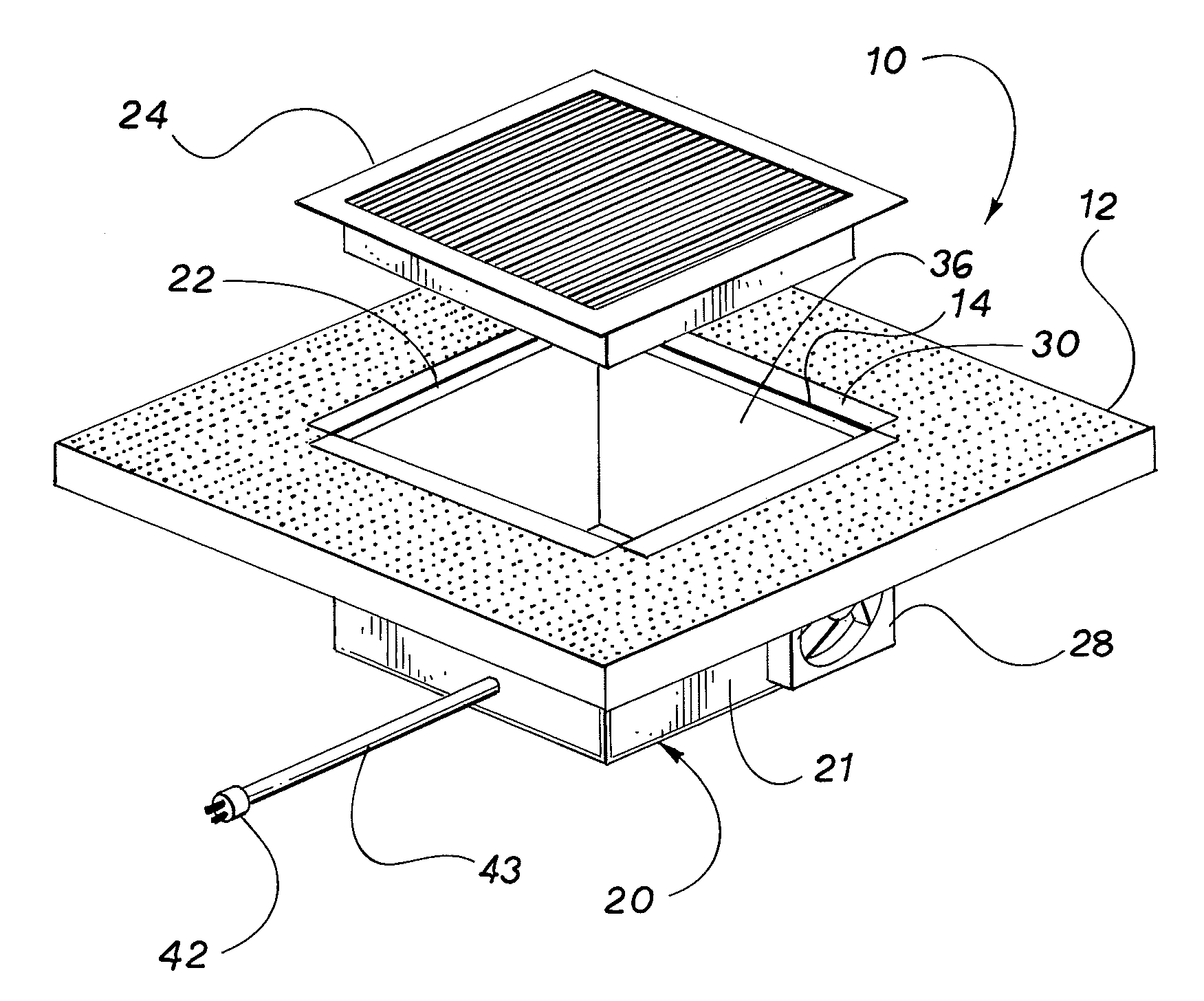
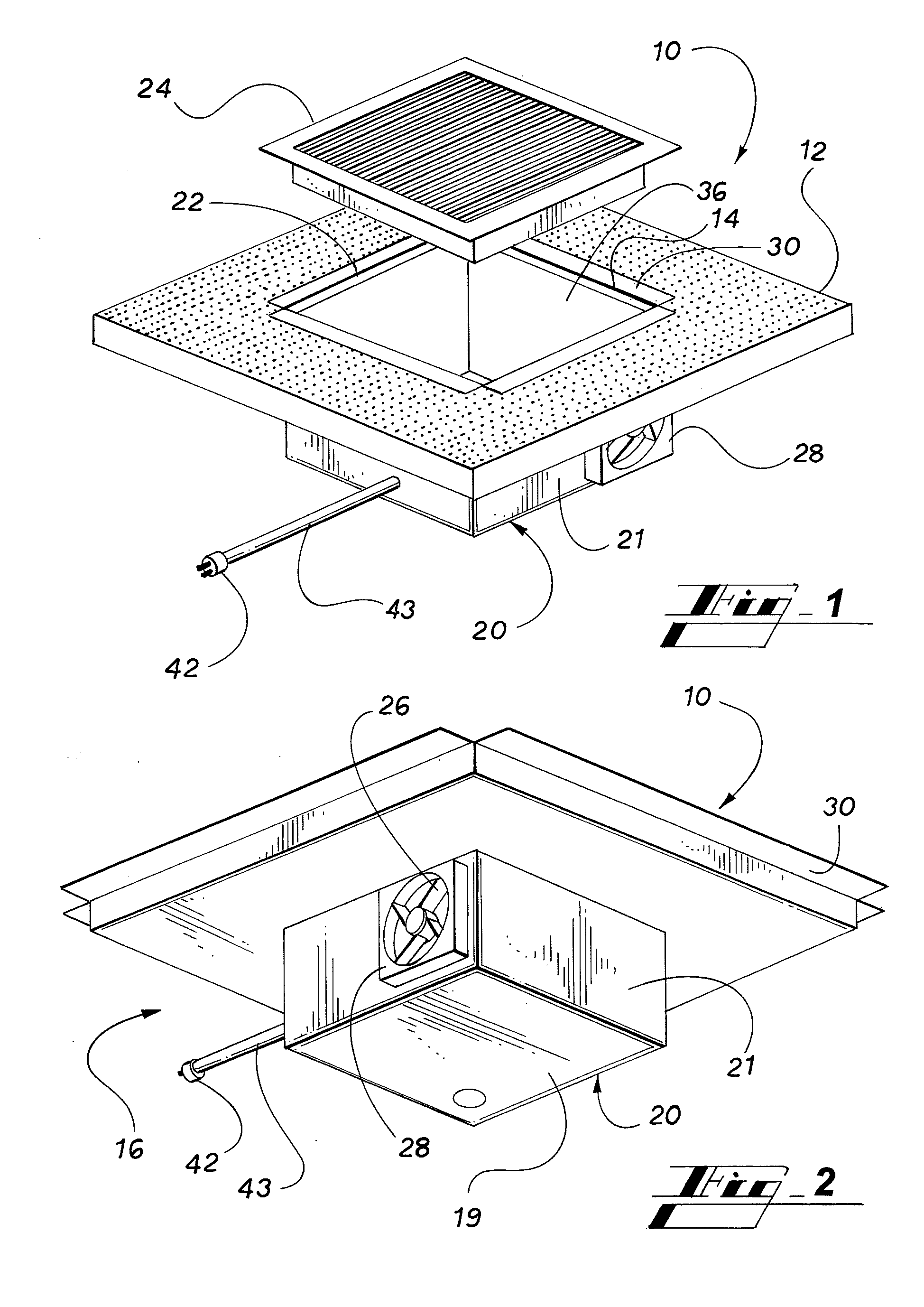
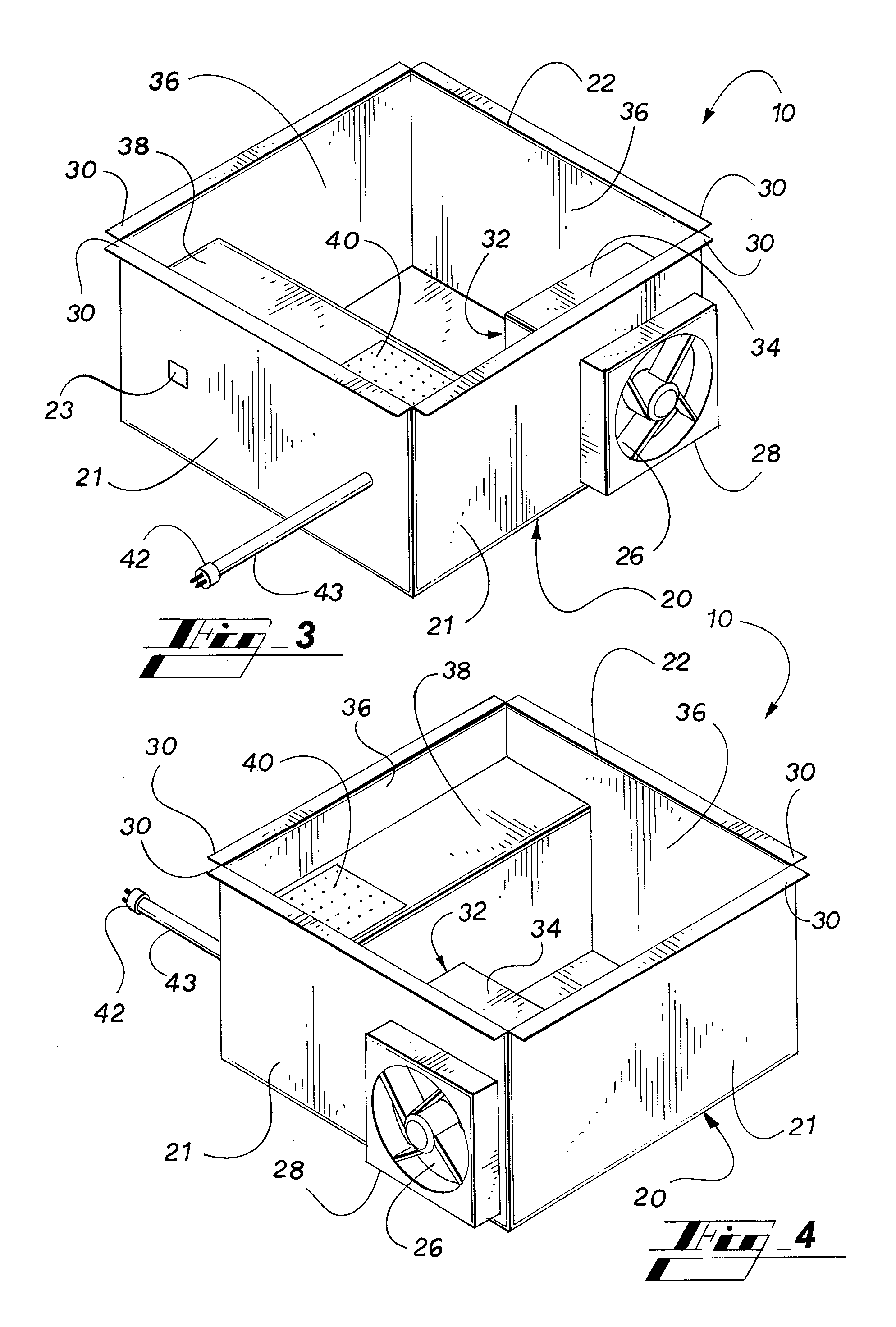
[0023] Referring now to the drawings, in which like reference numerals represent like parts throughout the several views, FIG. 1 discloses a floor ventilation diffuser 10 in accordance with the present invention mounted in a floor opening 14 of a floor 12. Conditioned air is supplied to a closed underfloor plenum 16 by means of a fan column (not shown). The floor ventilation diffuser 10 includes a diffuser housing 20 with side walls 21 and a bottom wall 19. The diffuser housing 20 has with an air outlet opening 22 and an air inlet opening 26 in one of side walls 21. A diffuser grille 24 is mounted over the air outlet opening 22. An inlet fan 28 is mounted in the air inlet opening 26.

[0024] The diffuser housing or plenum box 20 is constructed of galvanized steel or other suitable material to prevent oxidization after installation in the field. The diffuser housing 20 has a lip 30 on all four sides to allow the floor ventilation diffuser 10 to rest within the opening 14 in the raised...


PUM


Abstract

A fan assisted floor ventilation diffuser includes an enclosed diffuser housing with an air inlet opening and an air outlet opening. A diffuser grille covers the air outlet opening and an inlet fan is mounted at the air inlet opening. The inlet fan pulls air from the underfloor plenum into the floor ventilation diffuser housing and discharges the air through the diffuser grille into the occupied space. A thermostat in each room of the occupied space above the floor controls the operation of the inlet fan for each floor ventilation diffuser in the room and thereby controls the amount of air passing through the floor ventilation diffuser and into an individual room in the occupied space.

Description

CLAIM OF PRIORITY HIM OR HER [0001] This application claims priority from U.S. Provisional Patent Application Ser. No. 60 / 864,224, filed on Nov. 3, 2006, which is incorporated herein in their entirety.FIELD OF THE INVENTION [0002] The present invention relates to a floor ventilation diffuser with an inlet fan. The floor ventilation diffuser is used in an underfloor plenum air conditioning system. BACKGROUND OF THE INVENTION [0003] In an underfloor plenum air conditioning system, warm or cool air is supplied to the plenum below the floor of an occupied space that is to be heated or cooled. In order to heat or cool the occupied space above the floor, floor ventilation diffusers are mounted in the floor at predetermined locations to allow the warm or cool air in the plenum to flow into the occupied space above the floor. The floor ventilation diffusers are located and oriented to accommodate the configuration of the occupied space to be heated or cooled. [0004] Prior art floor ventilat...

Claims


Application Information

Patent Timeline
IPC IPC(8): F24F7/06F24F11/02
CPCF24F7/06F24F2221/40F24F13/06
Inventor RIMMER, JULIAN DOUGLASMCCORRISTER, ANDREW GARTH
Owner E H PRICE
Why Eureka
Try Eureka