Deployment tool for distal bone anchors with secondary compression

a distal bone anchor and distal bone technology, applied in the field of bone anchors, can solve the problems of introducing several significant problems, affecting the treatment effect, and affecting the quality of life of patients,

Inactive Publication Date: 2008-05-08
INTERVENTIONAL SPINE
View PDF48 Cites 152 Cited by
  • Summary
  • Abstract
  • Description
  • Claims
  • Application Information

AI Technical Summary

Benefits of technology

[0016] In yet another embodiment, a bone fixation device and deployment system is described. The system includes a bone fixation device comprising an elongate body having a proximal end and a distal end and comprising a first portion and a second portion which are detachably coupled to each other at a junction. The fixation device further includes a helical anchor on the distal end, a retention structure on the body proximal to the anchor, and an anti-rotational structure on the first portion of the body. The fixation device also includes a proximal anchor, movably carried by the body and comprising a tubular sleeve that in a first position extends distally past the junction between the first portion the second portion. The proximal anchor also has a rotational coupling. The proximal anchor is movable in the distal direction with respect to the body, the retention structure resists proximal movement of the proximal anchor with respect to the body and the anti-rotational structure prevents rotational movement of the first portion of the body with respect to the proximal anchor. The system further includes a deployment device comprising an elongate body having a distal end configured to engage the rotational coupling of the proximal anchor.

Problems solved by technology

However, portions of the femur are extremely susceptible to fracturing.
Fractures of the femur which extend into the neck of the bone are generally more difficult to treat than fractures restricted to the shaft of the femur.
The leading end portion of the implant typically includes means to positively grip the femoral head bone (external threads, expanding arms, etc.), but the inclusion of such gripping means can introduce several significant problems.
First, implants with sharp edges on the leading end portion, such as the externally threaded implants, exhibit a tendency to migrate proximally towards the hip joint weight bearing surface after implantation.
This can occur when the proximal cortical bone has insufficient integrity to resist distal movement of the screw head.
Such proximal migration under physiological loading, which is also referred to as femoral head cut-out, can lead to significant damage to the adjacent hip joint.
Also, the externally threaded implants can generate large stress concentrations in the bone during implantation which can lead to stripping of the threads formed in the bone and thus a weakened grip.
As a result, all fatigue loading is concentrated at the attached ends of the arms and undesirably large bending moments are realized at the points of attachment.
In addition, conventional threaded implants generally exhibit insufficient holding power under tension, such that the threads can be stripped out of the femoral head either by over-tightening during the implantation procedure or during post operative loading by the patient's weight.

Method used


Image

  • Deployment tool for distal bone anchors with secondary compression
  • Deployment tool for distal bone anchors with secondary compression
  • Deployment tool for distal bone anchors with secondary compression

Examples


Embodiment Construction

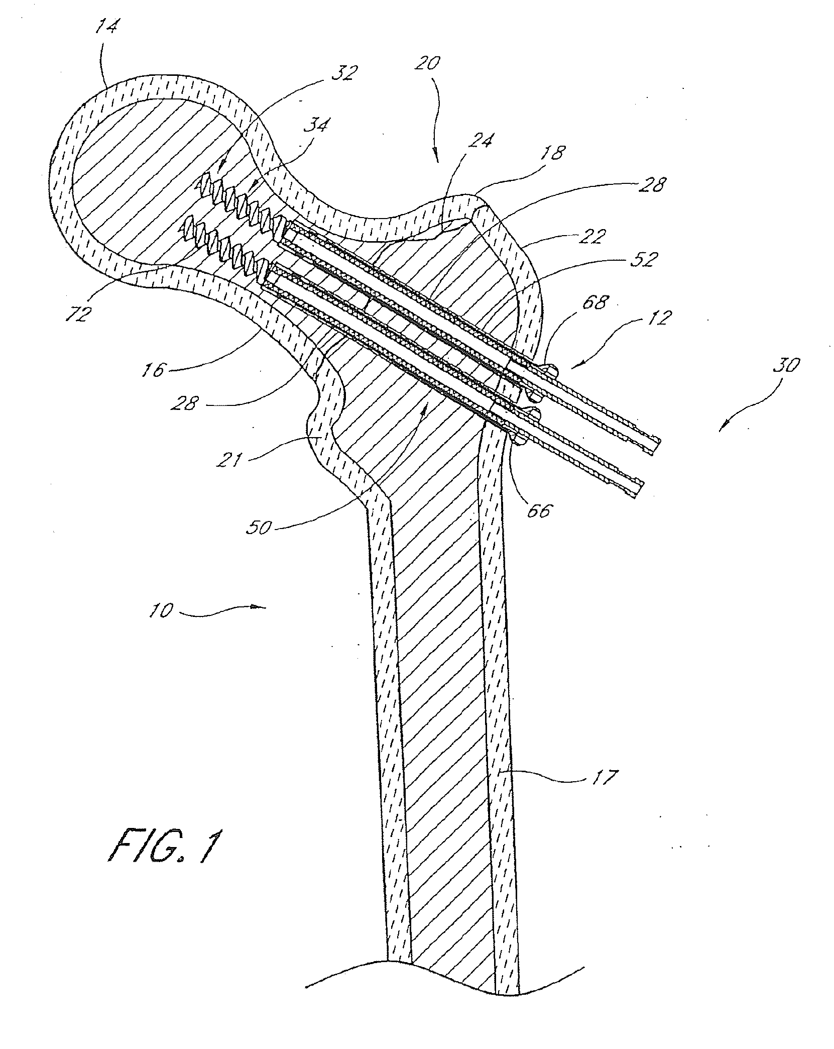
[0044] Although the fixation devices of the present invention will be disclosed primarily in the context of fractures of the proximal femur, the methods and structures disclosed herein are intended for application in any of a wide variety of bones and fractures, as will be apparent to those of skill in the art in view of the disclosure herein. For example, the bone fixation device of the present invention is applicable in a wide variety of fractures and osteotomies in the hand, such as interphalangeal and metacarpophalangeal arthrodesis, transverse phalangeal and metacarpal fracture fixation, spiral phalangeal and metacarpal fracture fixation, oblique phalangeal and metacarpal fracture fixation, intercondylar phalangeal and metacarpal fracture fixation, phalangeal and metacarpal osteotomy fixation as well as others known in the art. A wide variety of phalangeal and metatarsal osteotomies and fractures of the foot may also be stabilized using the bone fixation device of the present i...


PUM

PropertyMeasurementUnit
angleaaaaaaaaaa
diameteraaaaaaaaaa
lengthaaaaaaaaaa

Abstract

Deployment systems for deploying a bone fixation device are disclosed herein. One embodiment of a deployment system includes a syringe-shaped body configured to provide proximal traction to a bone fixation device in response to a compressive force between a finger grip and a plunger adapted to be engaged by the heel of a clinician's hand. The device may include a collet for gripping a proximal pin of a fixation device. The deployment device may also include a tool that includes an elongate body with a distal tip adapted to rotationally engage a bone fixation device in order to axially rotate the fixation device. A further deployment device embodiment includes a cauterizing tip for heat-cutting an excess portion of a pin of a bone fixation device.

Description

CROSS-REFERENCE TO RELATED APPLICATIONS [0001] The present application is a divisional of U.S. patent application Ser. No. 10 / 790,671, filed Mar. 1, 2004, which is a continuation-in-part of U.S. patent application Ser. No. 09 / 991,367, filed Nov. 13, 2001, now U.S. Pat. No. 6,890,333, which is a continuation-in-part of U.S. patent application Ser. No. 09 / 934,467, filed Aug. 23, 2001, now U.S. Pat. No. 6,551,481, and claims priority and benefit under 35 U.S.C. §119(e) of U.S. Provisional Patent Application Ser. No. 60 / 464,398, filed Apr. 21, 2003, and claims priority and benefit under 35 U.S.C. §119(e) of U.S. Provisional Patent Application Ser. No. 60 / 451,296, filed Feb. 28, 2003, the entireties of the disclosures of each of which are incorporated herein by reference.BACKGROUND [0002] 1. Field of the Invention [0003] The invention relates in general to the field of bone anchors, and specifically to a deployment device for a bone anchor. [0004] 2. Description of the Related Art [0005]...

Claims


Application Information

Patent Timeline
Patent Type & Authority Applications(United States)
IPC IPC(8): A61B17/78A61B17/00A61B17/56A61B17/74A61B17/86A61B17/88A61L
CPCA61B17/8685A61B17/869A61B17/88A61B17/8863A61B2017/00734A61B17/8872A61B17/8875A61B17/8883A61B17/8891A61B17/8869
Inventor PADGET, MARTINCULBERT, BRAD S.
Owner INTERVENTIONAL SPINE
Why Eureka
Try Eureka