Supercharge Your Innovation With Domain-Expert AI Agents!

Dryer Configured for Fresh Air Induction

a technology of fresh air and dryer, which is applied in the direction of drying machines, drying machines with progressive movements, drying machines, etc., can solve the problems of inefficient use of appliances, inability to adjust the condition of the air within the building, and inability to activate other less efficient devices

Inactive Publication Date: 2008-05-15
ROBERTSHAW CONTROLS CO
View PDF50 Cites 20 Cited by
  • Summary
  • Abstract
  • Description
  • Claims
  • Application Information

AI Technical Summary

Benefits of technology

The patent describes a new and improved dryer for drying moist goods that is designed to use air from outside the building where it is housed. This dryer can be attached to a duct that has both an air intake and an air exhaust passage separated by thermally conductive material, which increases the efficiency of the drying process. The dryer includes an air flow passage, a blower, and an air intake and exhaust manifold. The dryer can also be used with existing ductwork in buildings by retrofitting additional duct inside of existing duct to provide dual flow passages. The technical effects of this patent are improved drying efficiency, reduced energy usage, and increased flexibility in installation options.

Problems solved by technology

However, no matter how efficient some appliances are made, the use of the appliance may be inefficient by causing other less efficient devices to also activate.
This replacement of such a substantial volume of conditioned air from within the building with unconditioned air from the exterior of the building typically causes the condition of the air within the building to change.
Unfortunately, the HVAC system is the most costly system in most buildings to operate.
Thus, even if the individual operation of the clothes dryer can be made more efficient, the use of the clothes dryer causes the HVAC system to activate, reducing the overall efficiency of the clothes drying process.
Other problems exist with current clothes dryers.
For example, the exhaust duct that vents the exhaust air from the clothes dryer to the exterior of the building can become plugged with lint or other particulate and catch fire causing structural damage to the building.
Further, the exhaust pipes themselves can become extremely hot as a result of the hot exhaust air flowing through the pipes which can damage walls, wires, and other structure of the building that are positioned proximate the exhaust ducts.
In addition, as the clothes dryer expels the humid warmed air from the building, the humid warm air takes with it a large quantity of heat energy that has been produced by the dryer to dry the clothes.
This heat energy stored in the exhausted humid warm air is merely dumped into the exterior environment and wasted further reducing the overall operating efficiency.

Method used


Image

  • Dryer Configured for Fresh Air Induction
  • Dryer Configured for Fresh Air Induction
  • Dryer Configured for Fresh Air Induction

Examples


Embodiment Construction

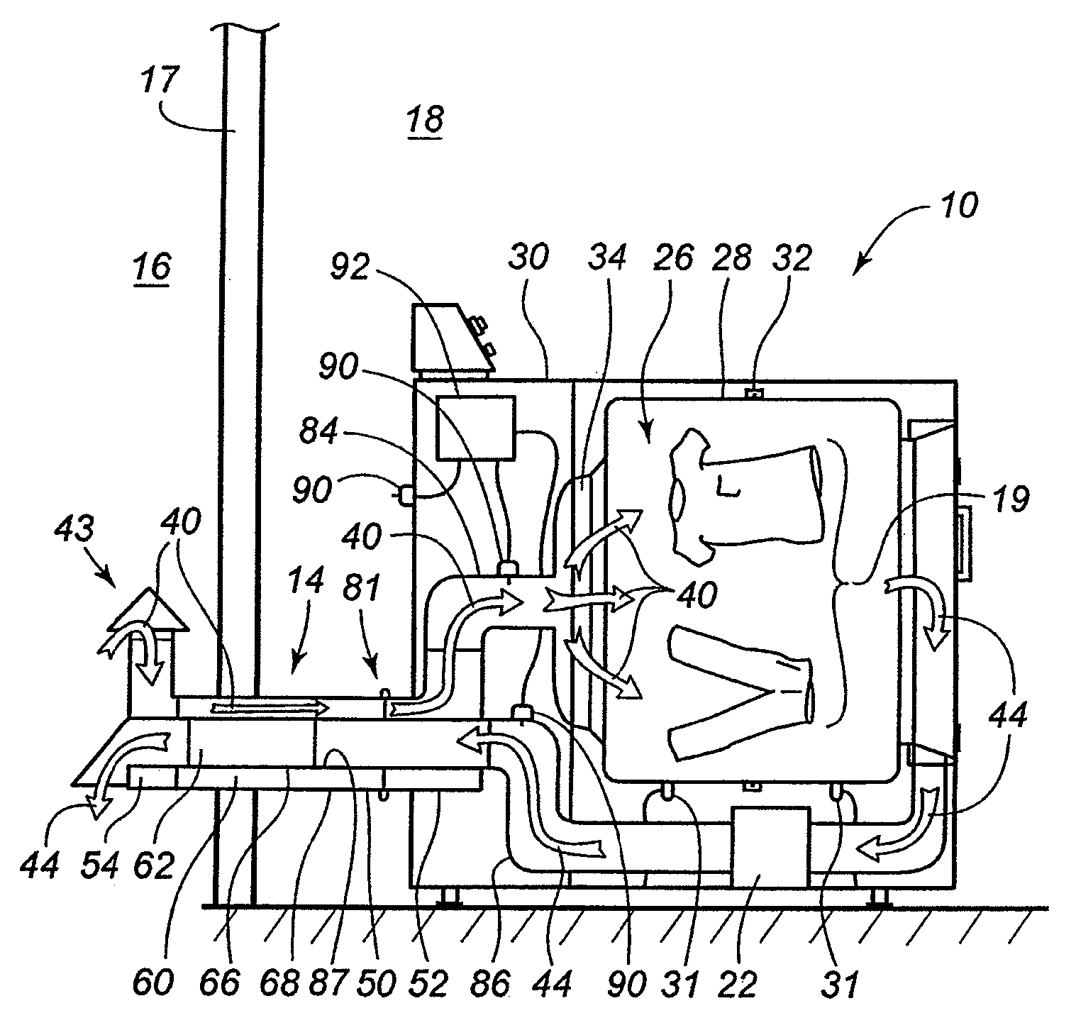
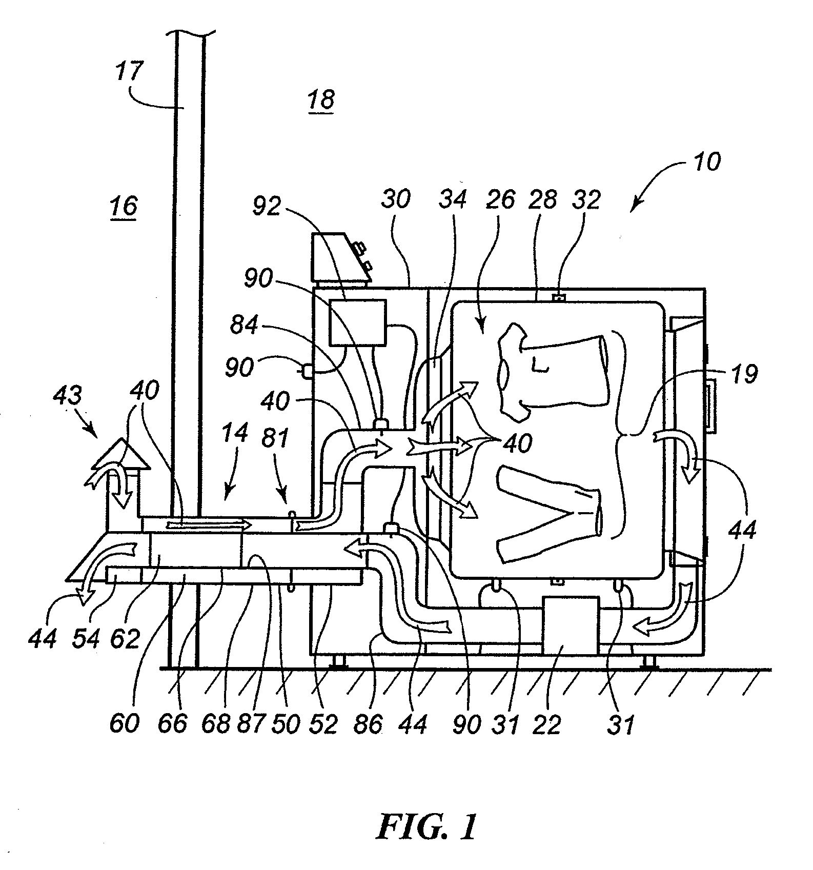
[0022]Turning now to the figures, FIG. 1 illustrates a dryer 10 and a dual flow duct 14 according to the teachings of an embodiment of the present invention. The dryer 10 advantageously draws air from the exterior 16 of the building 17 rather than conditioned air from the interior 18 of the building 17 to dry moist goods 19 within the dryer 10. This configuration significantly reduces the amount of conditioned air within the building 17 that is needlessly exhausted from the building 17 during a drying cycle and lost to the exterior 16 of the building 17. Advantageously, by reducing the amount of conditioned air that is exhausted from the building 17, the same amount of exterior, unconditioned air, is prevented from entering the building 17. By reducing the amount of unconditioned air that is added to the building 17, the internal conditions of the building 17 are not significantly altered during the drying process, thereby reducing the work load, and energy use, of the HVAC system o...


PUM


Abstract

A dryer for drying moist goods is provided. The dryer reduces the amount of conditioned air used during the drying cycle by drawing drying air from the exterior of the building rather than the interior of the building thereby reducing the overall energy efficiency of the building. The dryer includes an air flow passage extending between a fresh air inlet and an exhaust air outlet. A drying chamber forms a portion of the air flow passage and is interposed between the fresh air inlet and the exhaust air outlet. A blower moves air through the air flow passage. The fresh air inlet and exhaust air outlet are separated from one another by a common wall and are positioned adjacent to one another. The fresh air inlet and exhaust air outlet are configured to attach to a combined supply and exhaust duct such that exhaust air and fresh air are passed between the dryer and the exterior of the building through the combined supply and exhaust duct.

Description

FIELD OF THE INVENTION[0001]This invention generally relates to appliances and, more particularly, to dryers and drying systems for drying goods.BACKGROUND OF THE INVENTION[0002]With increasing energy costs, consumers are becoming more and more energy conscious. As such, consumers are demanding more energy efficiency from their appliances and the homes in which they live. Many appliance manufacturers have responded by attempting to increase their products' energy efficiency. However, no matter how efficient some appliances are made, the use of the appliance may be inefficient by causing other less efficient devices to also activate.[0003]One such example is the use of a dryer for drying moist articles or goods, commonly referred to as a clothes dryer. Common practice with clothes dryers is to intake air from the room in which the clothes dryer is operating, heat it, pass it through the moist goods housed in a drying chamber, also referred to as a drum, and then exhaust it from the c...

Claims


Application Information

Patent Timeline
Patent Type & Authority Applications(United States)
IPC IPC(8): F26B21/06F26B19/00D06F34/08
CPCD06F58/20D06F2058/2864D06F58/28D06F2103/36D06F2105/24D06F2103/28D06F2105/32D06F2103/00D06F34/08
Inventor EHLERS, GREGORY ALLEN
Owner ROBERTSHAW CONTROLS CO
Features
  • R&D
  • Intellectual Property
  • Life Sciences
  • Materials
  • Tech Scout
  • Unparalleled Data Quality
  • Higher Quality Content
  • 60% Fewer Hallucinations
Learn More