Hydraulic recoil buffer assembly

a buffer assembly and hydraulic technology, applied in the direction of muzzle attachment, butts, weapons, etc., can solve the problem of shooter fatigu

Active Publication Date: 2008-05-15
ENIDINE
View PDF25 Cites 70 Cited by
  • Summary
  • Abstract
  • Description
  • Claims
  • Application Information

AI Technical Summary

Problems solved by technology

This recoil imparts a load on the shoulder of the shooter which is not only uncomfortable, but over repeated firings can lead to fatigue of the shooter.

Method used


Image

  • Hydraulic recoil buffer assembly
  • Hydraulic recoil buffer assembly
  • Hydraulic recoil buffer assembly

Examples


Embodiment Construction

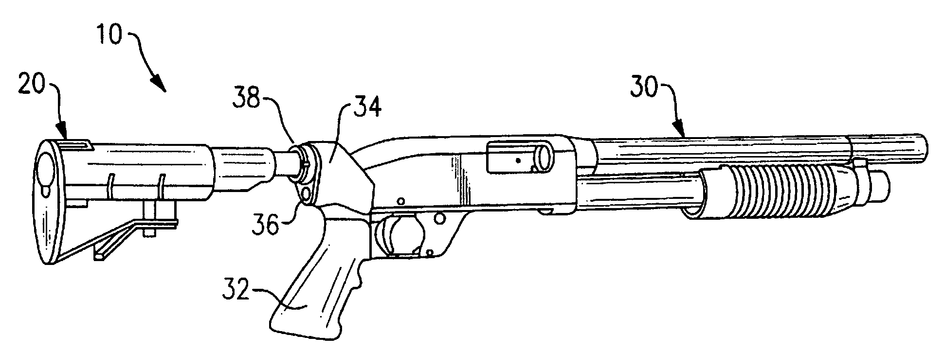
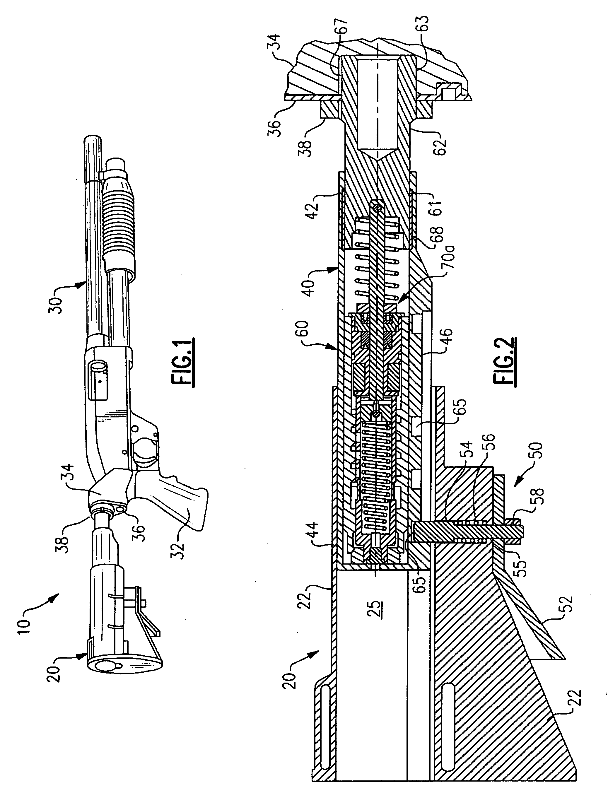
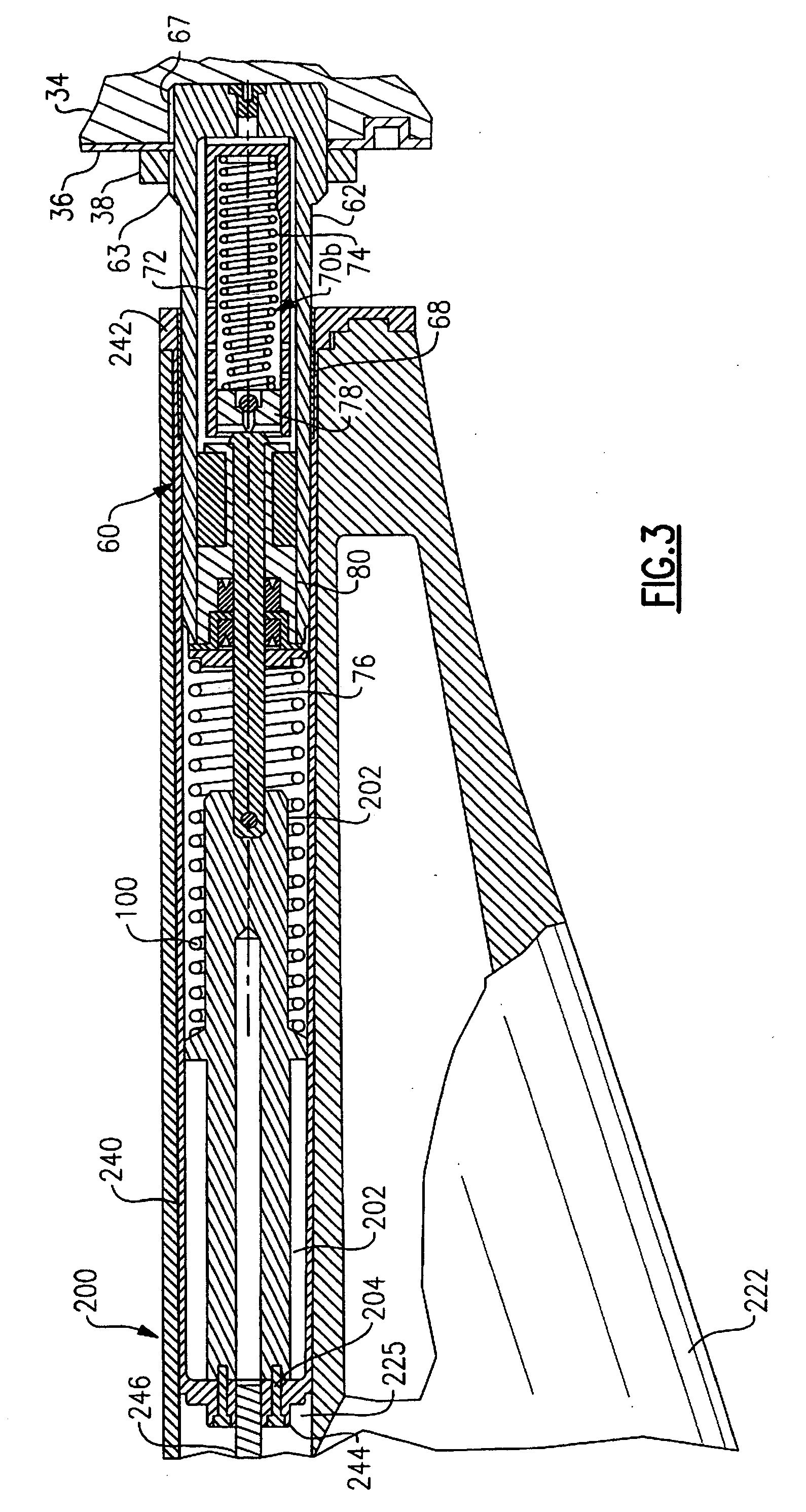
[0019]Referring now to FIGS. 1 and 2, there is depicted a tactical shotgun 10 having a collapsible stock assembly 20, a gun barrel 30 having a pistol grip 32 and a stock and pistol grip adaptor 34, and a hydraulic recoil buffer assembly 60 providing an interface between the collapsible stock assembly 20 and the stock and pistol grip adaptor 34. The collapsible stock assembly 20 includes an axially elongated extension tube 40 having an open forward end 42 and an aft end 44 that is slidably received into an axially extending cavity 25 in the buttstock 22 of the collapsible stock assembly 20. The cavity 25 extends coaxially with the extension tube 40 for the length of the buttstock 22. The hydraulic recoil buffer assembly 60 includes an end cylinder 62 having an aft end 61 disposed coaxially within forward end 42 of the extension tube 40 and a forward end 63 extending coaxially outward from the extension tube 40. The forward end 63 of the end cylinder 62 is provided with threads and is...


PUM


Abstract

A hydraulic recoil buffer assembly for a firearm having a receiver and a fixed or collapsible stock assembly including an end cylinder adapted to be secured to the pistol grip or receiver of the firearm and slidably translatable with respect to the extension tube, and a hydraulic shock absorption assembly operative to produce a hydraulic resistance to a rearward movement of the end cylinder during recoil of the firearm. The hydraulic shock absorption assembly has an orifice restricted fluid flow passage and a piston head that compresses a return spring as the end cylinder moves rearward against a recoil coil spring. The recoil buffer assembly stores a portion of the recoil energy through compression of the recoil spring and the return spring, and dissipates a portion of the recoil energy through the resistance provided by fluid flow through the orifice restricted flow passage.

Description

FIELD OF THE INVENTION[0001]This invention relates generally to recoil energy absorption in firearms and, more particularly, to a hydraulic recoil buffer assembly for use between the stock and the receiver or pistol grip of a shotgun or rifle or other shoulder-held firearm to dissipate the recoil energy associated with discharge of the firearm.BACKGROUND OF THE INVENTION[0002]When a shoulder-held firearm is discharged, a rearwardly directed recoil force is generated as a result of the force impulse created to accelerate the ammunition. This recoil imparts a load on the shoulder of the shooter which is not only uncomfortable, but over repeated firings can lead to fatigue of the shooter. Various energy absorption devices have heretofore been used in connection with firearms to dissipate the recoil energy produced upon discharge of the firearm. In one class of energy absorption devices heretofore proposed for use in reducing recoil impact, a recoil assembly is disposed in the firearm s...

Claims


Application Information

Patent Timeline
Patent Type & Authority Applications(United States)
IPC IPC(8): F41A21/36
CPCF41C23/06
Inventor BUCHOLTZ, BRIAN C.SHURMATZ, WILLIAM W.JOHANNES, GREGG F.
Owner ENIDINE
Why Eureka
Try Eureka