Engine Piston and Manufacture

a technology for internal combustion engines and pistons, which is applied to engine components, mechanical equipment, valve arrangements, etc., can solve the problems of limited manufacturing processes, pistons that have tended to have weight penalties, and difficulty in manufacturing a small one-piece piston capable of fulfilling such potential

Inactive Publication Date: 2008-05-15
PARKER DUNCAN +4
View PDF1 Cites 5 Cited by
  • Summary
  • Abstract
  • Description
  • Claims
  • Application Information

AI Technical Summary

Problems solved by technology

Pistons for internal combustion engines for mass market automobiles are manufactured in large numbers and subjected to cost constraints, which in turn place limits on manufacturing processes.
For heavy duty use, for example in compression ignition engines, it is known to manufacture pistons of steel, usually forged, but such pistons have tended to have a weight penalty, notwithstanding extensive machining operations to remove extraneous metal, and have thus far been restricted to large capacity, low-revving engines found in trucks and the like.
Although steel is a material having suitable properties, and has such strength that it could be used in relatively thin sections that mitigate most if not all of the weight penalty, there is difficulty in manufacturing a small one-piece piston that is capable of fulfilling such potential.
Even without such added complexity, it is believed that the number of separate parts and assembly operations required are not conducive to providing a small piston capable of operating within a modern small engine in a cost-effective manner.

Method used


Image

  • Engine Piston and Manufacture
  • Engine Piston and Manufacture
  • Engine Piston and Manufacture

Examples


Embodiment Construction

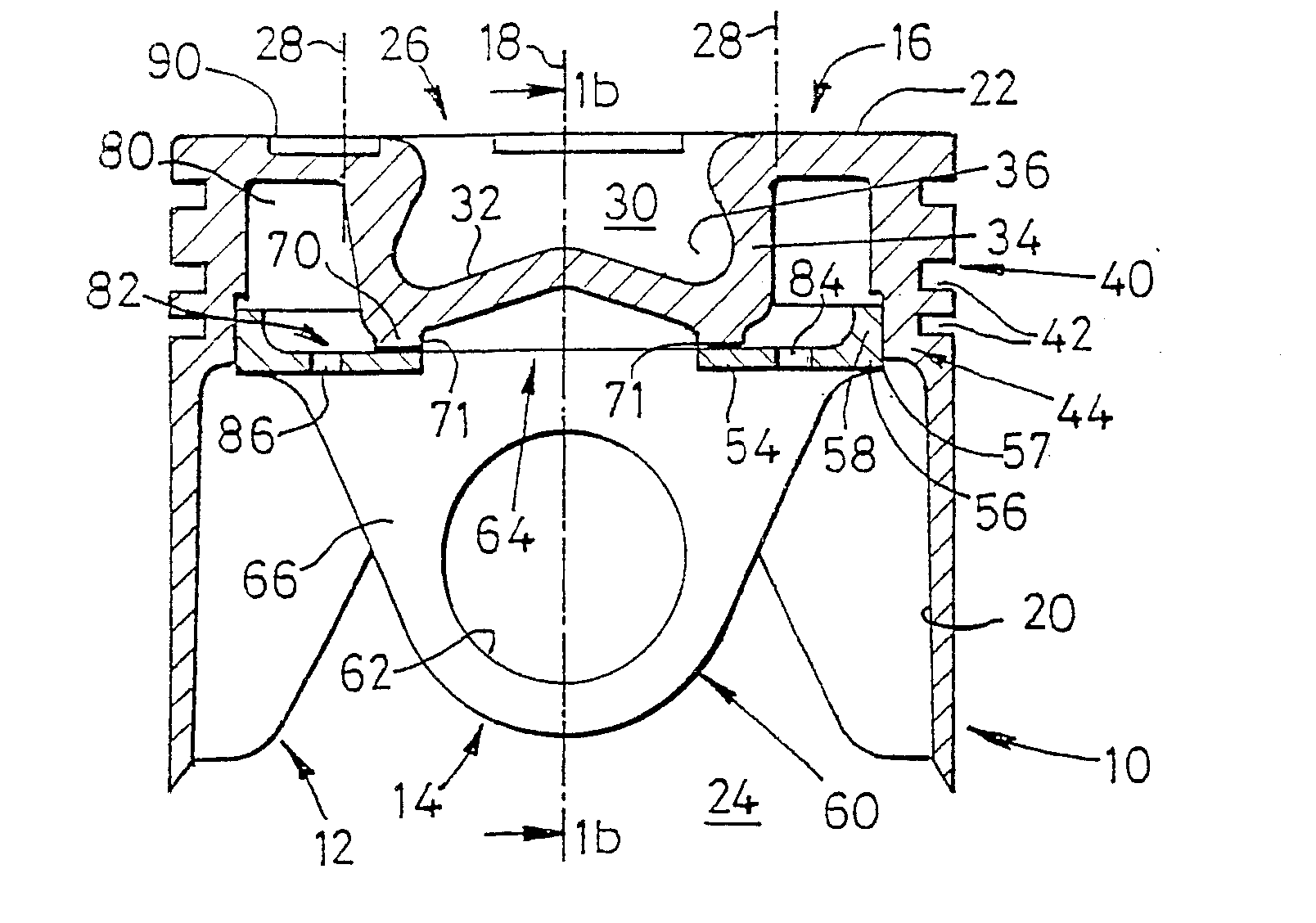
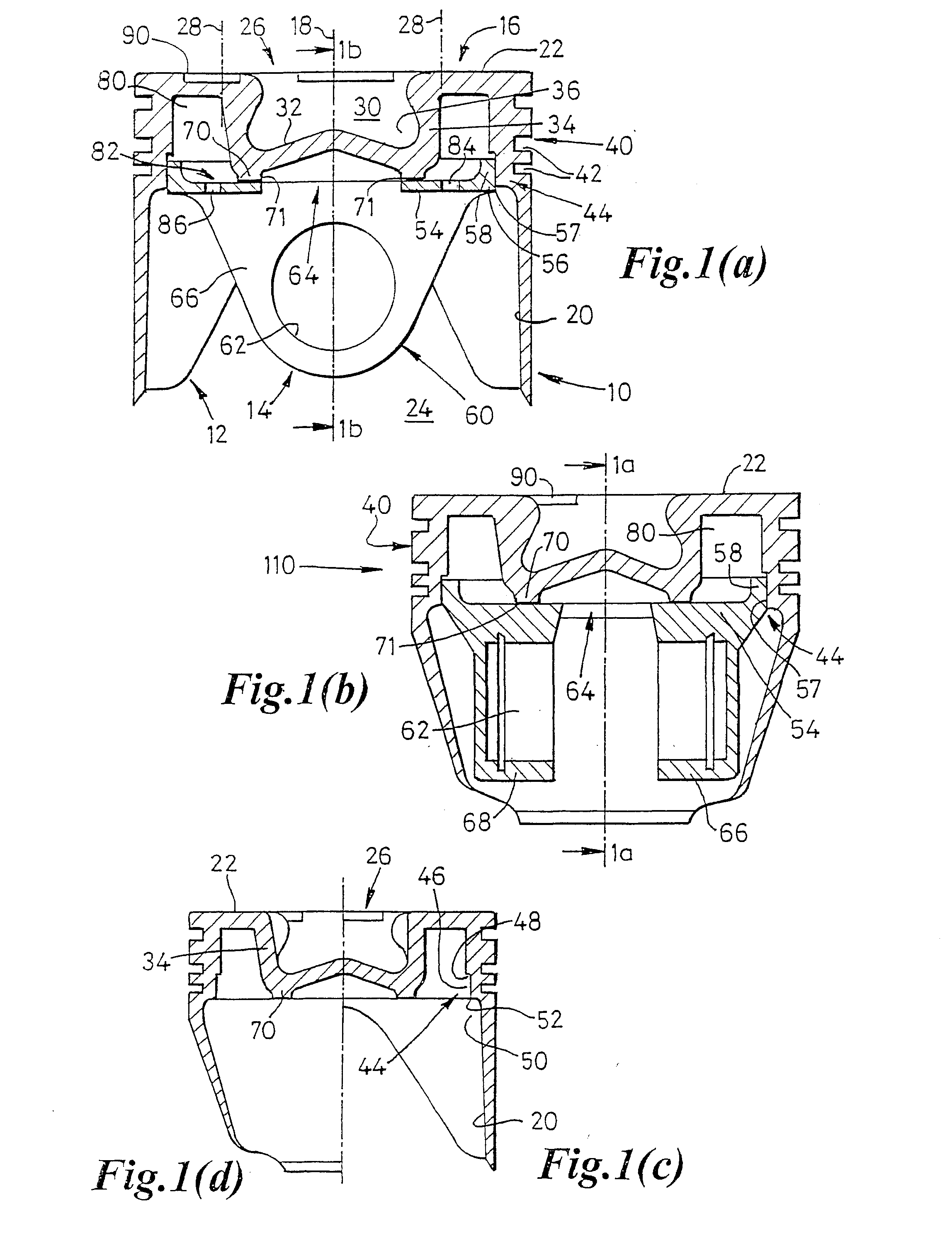
[0035] Referring to FIGS. 1(a) to 1(d) a piston 10 for an internal combustion engine is formed from high carbon steel. It comprises an outer shell 12 and a mounting member 14 bonded to it metallurgically by brazing.

[0036] The outer shell 12 comprises a crown 16 centred on a longitudinal piston axis 18, and a tubular side wall 20 extending axially with respect to peripheral region 22 of the crown to an open end 24.

[0037] Centrally of the crown, and surrounded by the peripheral region 22, is a central region 26 (denoted by boundary lines 28) in the form of a combustion bowl 30 having a bowl floor 32 displaced axially with respect to the crown peripheral region, and towards the open end of the tubular side wall, by a bowl wall 34. The bowl wall conveniently has a radially reentrant form as indicated at 36.

[0038] The crown 16, including both the central region 26 and peripheral region 22, is of integral formation with the tubular side wall by back extrusion onto a mandrel, as describ...


PUM

PropertyMeasurementUnit
heataaaaaaaaaa
weightaaaaaaaaaa
speedsaaaaaaaaaa

Abstract

An engine piston is manufactured by assembling an outer shell, comprising a crown and tubular side wall in which a ring groove region and skirt are defined, with a plate-like mounting member and bonding them together by brazing or welding. The mounting member is located within the tubular side wall displaced axially from the crown and is bonded near, but displaced radially from, its centre to the crown and at its periphery to the side wall at the end of the ring groove region. The mounting member carries gudgeon pin boss means facing away from the crown. The outer shell is formed by extrusion or the like that permits minimal wall thickness and the bonded structure is of light weight but great strength and stiffness, particularly in the ring groove region. A combustion bowl formed in the crown facilitates bonding to the mounting member and defines with the mounting member an annular cooling chamber adjacent the ring groove region and crown.

Description

RELATED APPLICATIONS [0001] This patent application is a divisional of U.S. patent application Ser. No. 10 / 343,499, filed Mar. 15, 2004, currently allowed, which claims priority to PCT / GB01 / 03361 filed Jul. 26, 2001 which claims priority to GB0018840.9 filed Aug. 2, 2000, all of which are incorporated herein by reference.STATEMENT REGARDING FEDERALLY SPONSORED RESEARCH [0002] NONE BACKGROUND OF THE INVENTION [0003] This invention relates to pistons for internal combustion engines and to the manufacture thereof. The invention is particularly concerned with the manufacture of a strong piston that is also light in weight and suitable for cost-effective mass production for small capacity, high compression engines. [0004] Pistons for internal combustion engines for mass market automobiles are manufactured in large numbers and subjected to cost constraints, which in turn place limits on manufacturing processes. Such pistons are usually, but not necessarily, cast from a light metal alloy, ...

Claims


Application Information

Patent Timeline
Patent Type & Authority Applications(United States)
IPC IPC(8): F02F3/00F02B23/06F02F3/16F02F3/20F02F3/22F02F3/26F16J1/00
CPCF02B23/0672F02F3/003F02F3/22F02F2200/04Y10T29/49249F05C2251/042Y02T10/125Y10T29/49256Y10T29/49252F05C2201/021Y02T10/12
Inventor PARKER, DUNCANPINDAR, DAVID THORNTONJONES, ROGER JAMESHUME, GILLIANTHARRATT, DAVID JAMES
Owner PARKER DUNCAN
Why Eureka
Try Eureka