Cylinder head
- Summary
- Abstract
- Description
- Claims
- Application Information
AI Technical Summary
Benefits of technology
Problems solved by technology
Method used
Image
Examples
Embodiment Construction
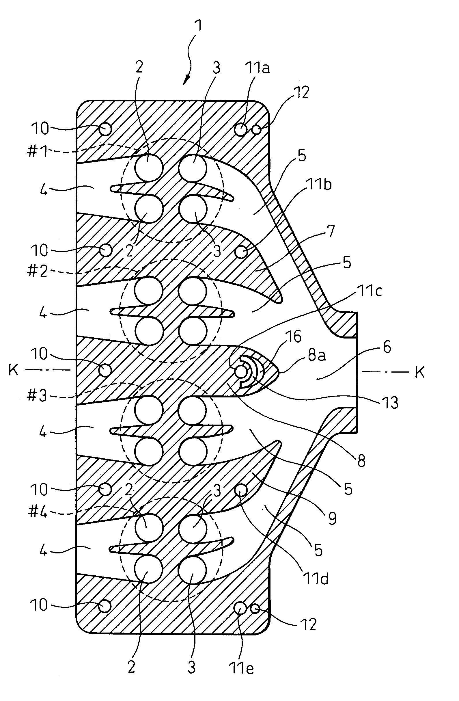
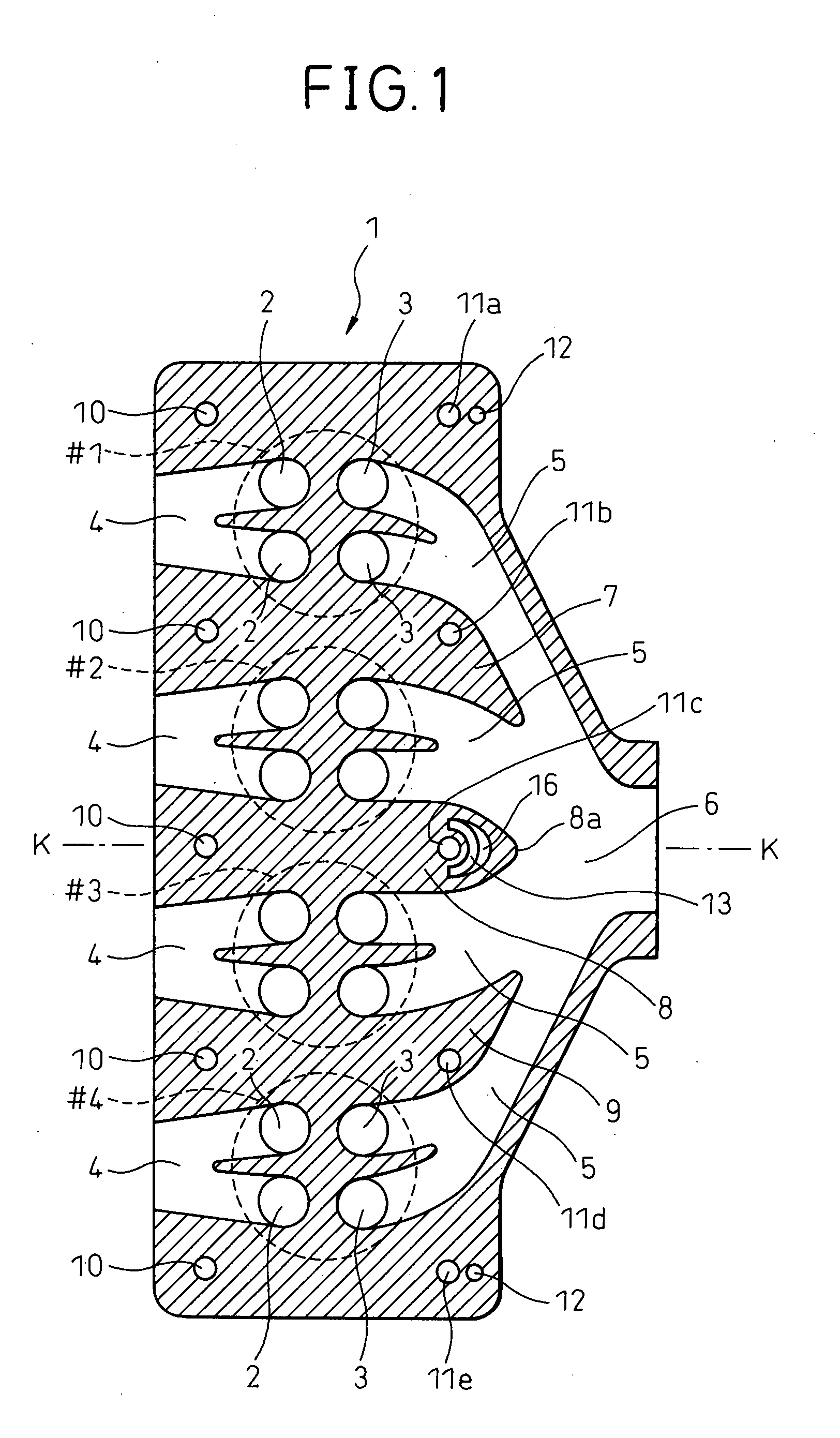
[0019]FIG. 1 is a cross-sectional plan view of a cylinder head 1 cast integrally from for example an aluminum alloy. Note that in FIG. 1, the circles shown by the broken lines show the positions of the No. 1 cylinder #1, No. 2 cylinder #2, No. 3 cylinder #3, and No. 4 cylinder #4. Therefore, it will be understood that the internal combustion engine provided with the cylinder head 1 shown in FIG. 1 is an in-line four-cylinder internal combustion engine. In FIG. 1, 2 indicate valve ports opened and closed by intake valves, while 3 indicate valve ports opened and closed by exhaust valves. Therefore, it will be understood that each of the cylinders #1, #2, #3, and #4 is provided with a pair of intake valves and a pair of exhaust valves.
[0020]Note that the cylinder head 1 is actually formed with cooling water passages extending along complicated paths, support parts of the valve mechanisms, insertion holes for the spark plugs, insertion holes for the fuel injectors, etc., but these are o...
PUM
 Abstract
Description
Claims
Application Information
 - R&D
- Intellectual Property
- Life Sciences
- Materials
- Tech Scout
- Unparalleled Data Quality
- Higher Quality Content
- 60% Fewer Hallucinations
Browse by: Latest US Patents, China's latest patents, Technical Efficacy Thesaurus, Application Domain, Technology Topic, Popular Technical Reports.
© 2025 PatSnap. All rights reserved.Legal|Privacy policy|Modern Slavery Act Transparency Statement|Sitemap|About US| Contact US: help@patsnap.com


