
Large bore packer and methods of setting same

a packer and large bore technology, applied in the direction of sealing/packing, wellbore/well accessories, drilling pipes, etc., can solve the problems of loss of inch of diameter in usable area, reduce the usable diameter within the well, etc., to save useable cross-sectional area, reduce the useable area, and increase the diameter

Inactive Publication Date: 2008-05-15
BAKER HUGHES INC
View PDF16 Cites 42 Cited by
  • Summary
  • Abstract
  • Description
  • Claims
  • Application Information

AI Technical Summary

Benefits of technology

[0006]The invention provides devices and methods for setting a packer inside a wellbore with little appreciable reduction of the useable area of the wellbore. In described embodiments, the outer casing or liner of the wellbore contains one or more integrated casing coupler joints having an increased diameter chamber portion. A large bore packing element is carried within the increased diameter chamber portion. The pack...

Problems solved by technology

Unfortunately, conventional packers and techniques for setting packers results in a reduction of usable diameter within the well.
However, the components of the packer device (including slips, elastomeric seals, setting sleeves and so forth) inherently occupy space between the inner and outer tubulars.
Over an inch of diameter in usable area is lost due to the presence of both the inner production tubing string and the packer device that is set within the space between the production tubing string and the casing.

Method used


Image

  • Large bore packer and methods of setting same
  • Large bore packer and methods of setting same
  • Large bore packer and methods of setting same

Examples


Embodiment Construction

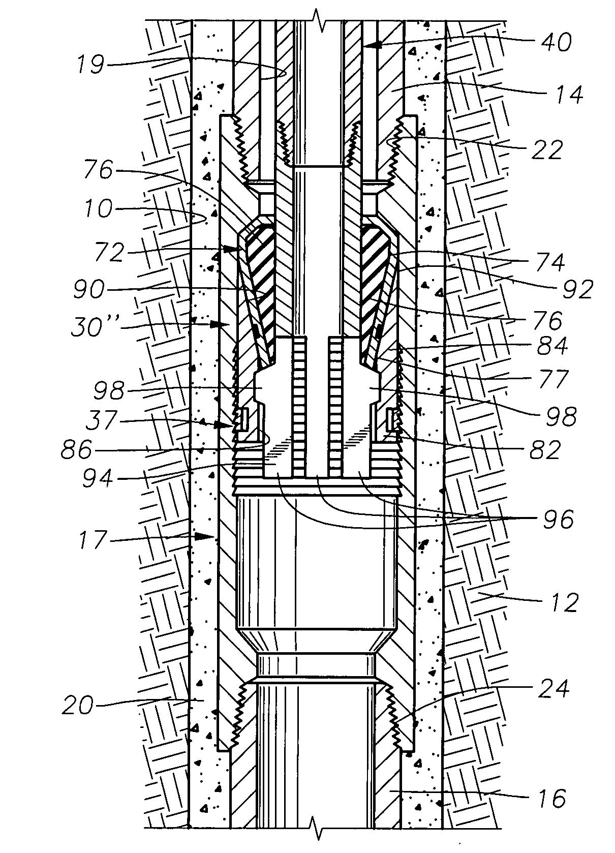
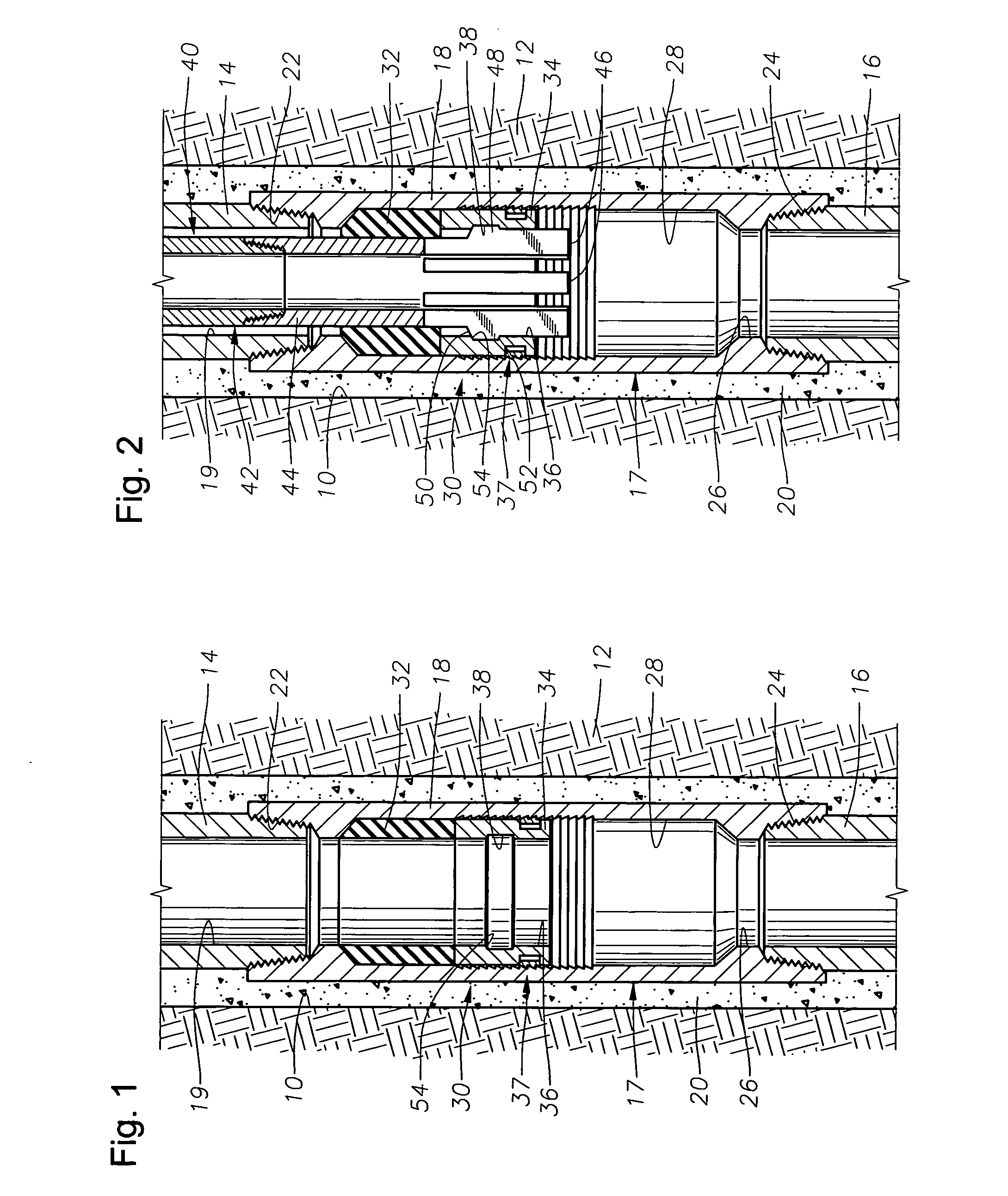
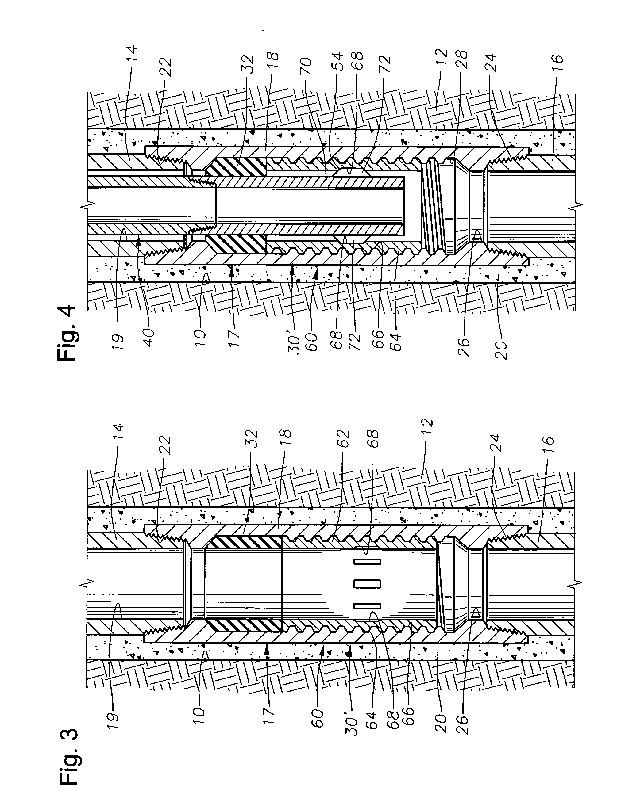
[0024]FIGS. 1 and 2 illustrate an exemplary wellbore 10 that has been drilled through the earth 12. The wellbore 10 is lined with a string of casing, of which two casing sections 14, 16 are depicted. A casing coupler 18 interconnects the casing sections 14, 16 to form a casing string 17 that defines a central bore 19 along its length. Cement 20 surrounds the casing sections 14, 16 and casing coupler 18. It is noted that the casing coupler 18 has a greater diameter than the casing sections 14, 16 and is secured to each of the casing sections 14, 16 via threaded connections 22, 24, respectively.

[0025]The casing coupler 18 includes an axial bore 26 for passage of tools and fluid through the casing coupler 18. The bore 26 has an enlarged diameter chamber portion 28. A packer device 30 is disposed within the enlarged diameter chamber portion 28. The packer device 30 includes a cylindrical elastomeric packer sealing element 32 and a cylindrical setting sleeve 34. The setting sleeve 34 is ...


PUM


Abstract

Devices and methods for setting a packer inside a wellbore with little appreciable reduction of the useable area of the wellbore. The outer casing or liner of the wellbore contains one or more integrated casing coupler joints having an increased diameter chamber portion. A large bore packing element is carried within the increased diameter chamber portion. The packing element may be selectively actuated to form a seal against an interior tubular member. Because the packing element is located within the chamber portion of the casing coupler, the packer may be set while saving useable cross-sectional area within the casing.

Description

BACKGROUND OF THE INVENTION[0001]1. Field of the Invention[0002]The invention relates generally to methods and packer devices that can be set within a wellbore with little or no reduction in useable cross-sectional bore area.[0003]2. Description of the Related Art[0004]Wellbore packers are used for securing production tubing inside of casing or a liner within a wellbore. Packers are also used to create separate zones within a wellbore. Unfortunately, conventional packers and techniques for setting packers results in a reduction of usable diameter within the well. This is because the packer is carried by a conveyance tubular (such as a production tubing string) that is of smaller diameter than the tubing or casing against which it is set. The packer is then set within the annular space between the conveyance tubular and the outer tubing or casing. Once set, the useable diameter of the well (i.e., the diameter through which production fluid can flow or tools can be passed) becomes the...

Claims


Application Information

Patent Timeline
IPC IPC(8): E21B33/12
CPCE21B17/08E21B23/02E21B23/06E21B33/1208E21B47/122E21B33/1285E21B33/134E21B43/105E21B33/128E21B47/13E21B33/0422E21B33/12E21B43/10E21B33/1212
Inventor RICHARD, BENNETT M.O'MALLEY, EDWARDXU, YANGFAY, PETERURBAN, LARRY
Owner BAKER HUGHES INC
Learn More