Elevator

a technology for elevators and guiding units, applied in the field of elevators, can solve the problems of guiding units colliding with guide rails, elevator cars being swung or elevator cars being swung, etc., and achieve the effects of preventing both the occurrence of resonance and the reduction of stability of a control system, reducing the amount of power, and high rigidity

Inactive Publication Date: 2008-05-15
TOSHIBA ELEVATOR KK
View PDF13 Cites 9 Cited by
  • Summary
  • Abstract
  • Description
  • Claims
  • Application Information

AI Technical Summary

Benefits of technology

[0015]In order to solve the above-mentioned problem, an object of the present invention is to provide an elevator capable of supporting an elevator car with high rigidity when the elevator car is stopped.
[0016]Another object to the present

Problems solved by technology

However, if supporting the elevator car with low rigidity even when it is stopped, there arises a problem that an application of a relatively-large load on the elevator car in the horiz

Method used


Image

  • Elevator
  • Elevator
  • Elevator

Examples


first embodiment

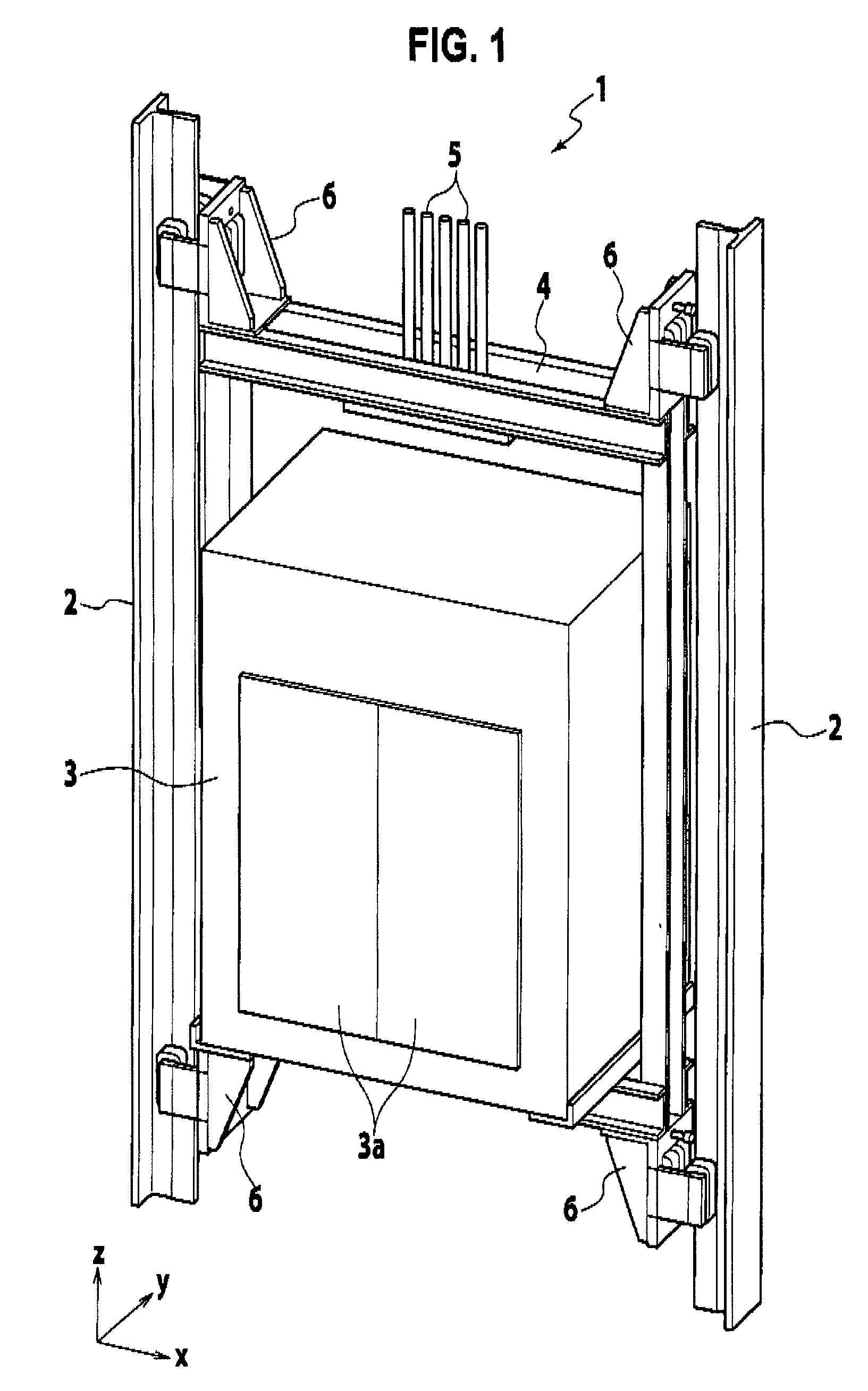
[0036]FIG. 1 is a perspective view showing an elevator in accordance with the present invention.

[0037]Inside an elevator shaft 1 in the same figure, there are vertically laid a pair of iron guide rails 2 made of ferromagnetic bodies and having a T-shaped cross section.

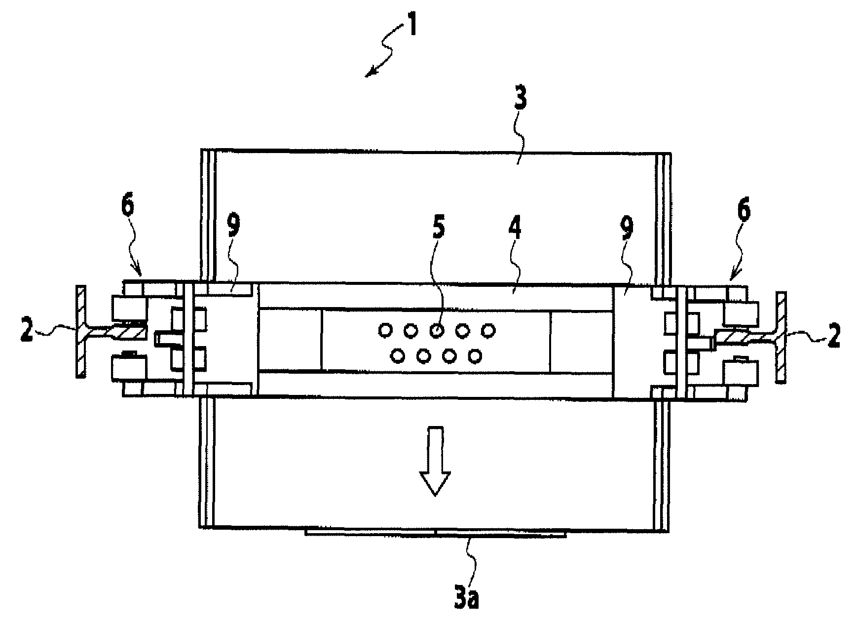
[0038]An elevator car 3 is fixed, on both sides thereof, to an inner side of a frame part 4 providing a rectangular framework. The elevator car 3 has a front door 3a arranged to oppose an elevator hall and is suspended in the elevator shaft 1 by ropes 5 which are connected to an upper part of the flame part 4 through respective one ends. With the arrangement, the elevator car 3 moves up and down in the elevator shaft 1 owing to driving means, for example, a rope lift-duty machine.

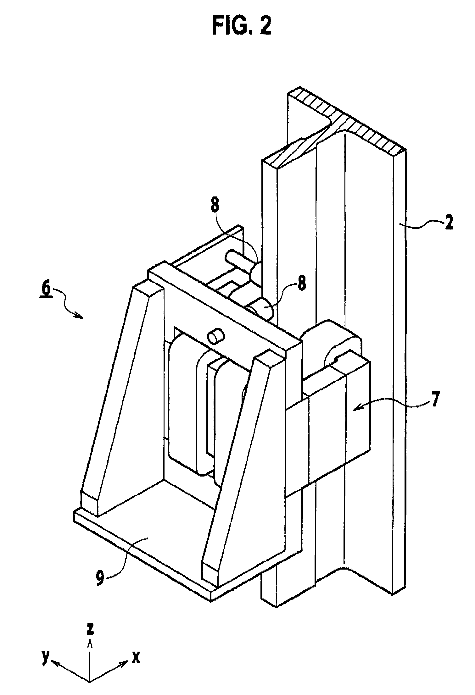
[0039]Guiding units 6 are fixed on four upper and lower corners of the frame part 4 so as to oppose the guide rails 2. Using these guiding units 6, the elevator car 3 is guided so as to be movable up and down along the guide rails 2.

[0040]As s...

third embodiment

[0068]Next the operation of the elevator in accordance with the third embodiment will be described with reference to FIG. 11. In this embodiment, the levitating operation is started when the door 3a begins to close under the stop of the elevator car 3 (time C1). After closing the door 3a and before the elevator car 3 travels (time C3), the guiding units 6 are brought into its stable levitating state and thereafter, the elevator car 3 starts traveling. On the other hand, after arriving at a destination floor, it is performed upon the stop of the elevator car 3 to open the door 3 a while allowing the guiding units 6 to attract the guide rail 2 gradually. With such an operation also, it is possible to shorten a time period between the closing / opening of the door 3a and the traveling of the elevator car 3.

[0069]Next, the operation of the elevator in accordance with the fourth embodiment will be described with reference to FIG. 12. In this embodiment, the operation of the third embodimen...


PUM


Abstract

An elevator includes guide rails (2) laid in an elevator shaft vertically, an elevator car (3) moving up and down along the guide rails, guiding units (6) provided on the elevator car for guiding it, the guiding unit having a magnet unit including cores (11) and coils (12) forming electromagnets to generate a magnetic force against the guide rail through an air gap and a controller (21) for controlling the magnetic force by maneuvering an exciting current for exciting the electromagnets. The controller (21) controls the magnetic force so as to make the guiding units in non-contact with the guide rails when the elevator car is traveling and brings the guiding units into contact with the guide rails when the elevator car is stopped, so that the guiding units attract and fix the guide rails while the elevator car is stopped.

Description

TECHNICAL FIELD[0001]The present invention relates to an improvement of an elevator that is adapted so as to guide an elevator car in non-contact with guide rails.BACKGROUND OF ART[0002]In an elevator, generally, an elevator car suspended by a rope moves up and down along a pair of guide rails laid in an elevator shaft vertically. Although the elevator car swings due to disequilibrium of loads or movements of passengers, these swing movements are suppressed since the elevator's traveling is guided by the guide rails.[0003]As for guiding units for an elevator car, either roller guides having wheels rolling on the guide rail and suspensions or guide shoes sliding on the guide rail have been adopted in the past. In a contact-type guide like this, however, there is a case that the amenity of an elevator is damaged since vibration and noise originating in a distortion of the guide and its joints are transmitted to the interior of the elevator car through the guiding units, or due to roll...

Claims


Application Information

Patent Timeline
IPC IPC(8): B66B1/34
CPCB66B7/044
Inventor ITO, HIROAKIMORISHITA, MIMPEI
Owner TOSHIBA ELEVATOR KK
Why Eureka
Try Eureka