

Carrying device
- Summary
- Abstract
- Description
- Claims
- Application Information
AI Technical Summary
Benefits of technology
Problems solved by technology
Method used
Image

Examples
Embodiment Construction
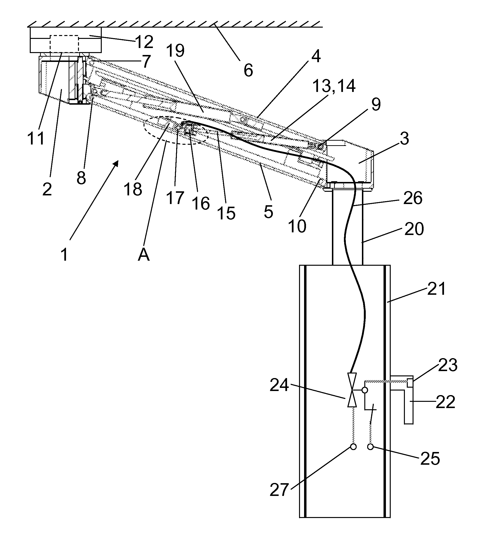
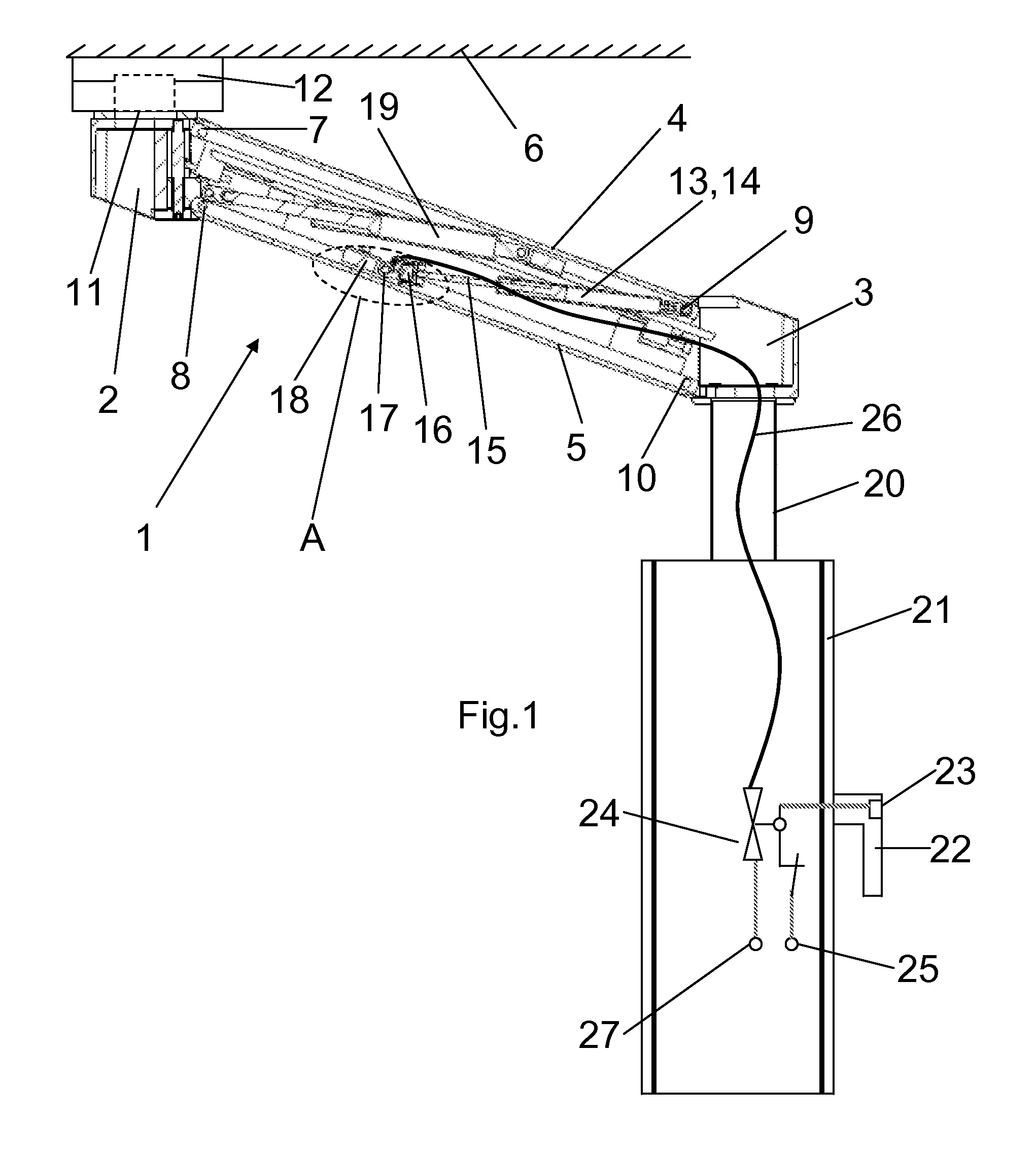
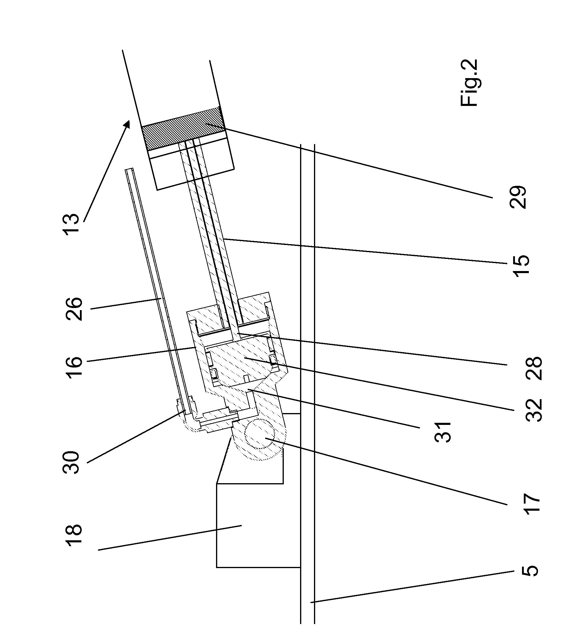
[0020]Referring to the drawings in particular, FIG. 1 schematically shows a longitudinal section of a bracket 1, which comprises a first head piece 2, a second head piece 3, a first bracket leg 4, a second bracket leg 5 and a pneumatic spring 13. The bracket legs 4, 5 are connected in the form of a parallelogram cranking mechanism to the head pieces 2, 3 via pin joints 7, 8, 9, 10. The first head piece 2 is fastened to the ceiling 6 of a treatment room via a hinge 11 with a ceiling flange 12. A self-locking pneumatic spring 13, whose piston sleeve 14 is connected to the pin joint 9, is located between the upper pin joint 9 at the second head piece 3 and the second bracket leg 5. The pneumatic spring 13 may be of the type disclosed in GB 2, 178, 508 A (which is incorporated by reference in its entirety) wherein the lifter 28 includes a valve 29 with a sealing cone and the spring arrangement presses the sealing cone on a valve seat of the valve 29. As the pneumatic spring 6 is a self ...
PUM
 Abstract
Description
Claims
Application Information