Downhole measurement of substances in earth formations

a technology of earth formations and substances, applied in the direction of optical prospecting, optical radiation measurement, borehole/well accessories, etc., can solve the problem of relatively weak signal

Inactive Publication Date: 2008-05-15
SCHLUMBERGER TECH CORP
View PDF20 Cites 70 Cited by
  • Summary
  • Abstract
  • Description
  • Claims
  • Application Information

AI Technical Summary

Problems solved by technology

Another difficulty with Raman spectroscopy is that the signal is relatively weak because only about one in a million source photons will undergo Raman scattering.

Method used


Image

  • Downhole measurement of substances in earth formations
  • Downhole measurement of substances in earth formations
  • Downhole measurement of substances in earth formations

Examples


Embodiment Construction

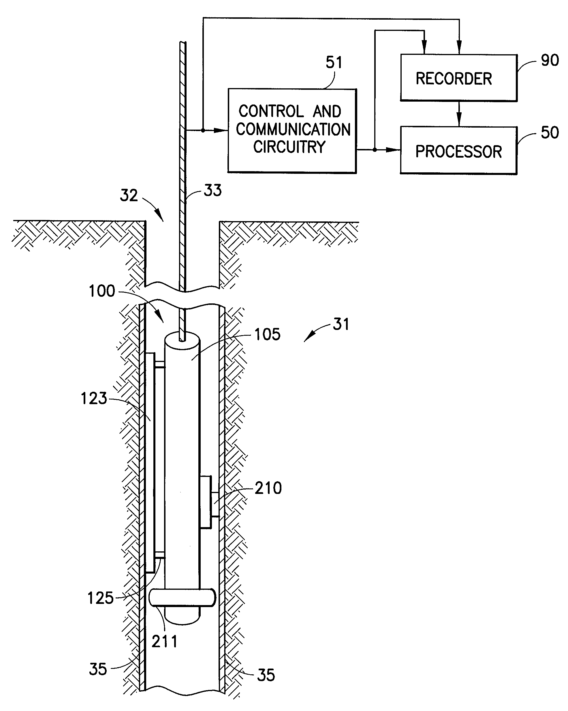
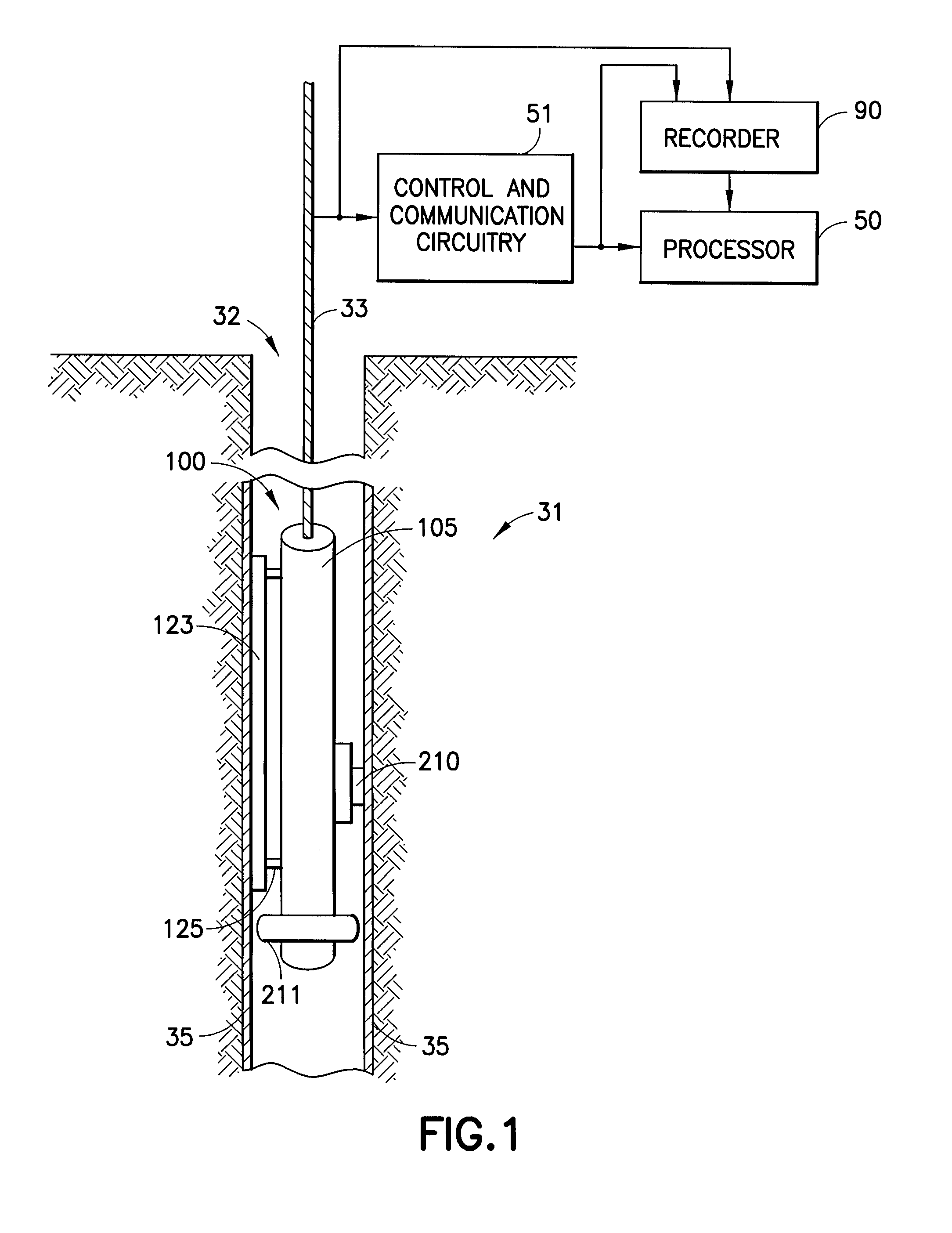
[0021]Referring to FIG. 1 there is shown a representative embodiment of a so-called “formation testing” apparatus for investigating subsurface formations 31 traversed by a borehole 32, of a type which, when modified as described herein, can be used in practicing embodiments of the invention. Formation testing logging devices are described, for example, in the above-referenced U.S. Pat. Nos. 3,859,851, 3,789,575, 3,934,468 and 4,860,581, and in Badry et al., “Downhole Optical Analysis of Formation Fluids,” Oilfield Review, pp. 21-28, January, 1994. The borehole 32 is typically filled with drilling fluid or mud which contains finely divided solids in suspension. A mudcake on the borehole wall is represented at 35. The investigating apparatus or logging device 100 is suspended in the borehole 32 on an armored multiconductor cable 33, the length of which substantially determines the depth of the device 100. Known depth gauge apparatus (not shown) is provided to measure cable displacemen...


PUM


Abstract

A method for determining a property of earth formations surrounding a borehole, including the following steps: isolating a region of the borehole, and obtaining a sample of borehole fluid from the isolated region; and implementing measurements, dowhole, of the Raman scattering of electromagnetic energy directed at the fluid sample; the property of the earth formations being determinable from the measurements. In a disclosed embodiment, the steps of isolating a region of the borehole and obtaining a sample of borehole fluid from the isolated region include: providing a logging device in the borehole in sealing engagement with the isolated region, causing formation fluid from the isolated region to flow in a flow line of the logging device, and providing a measurement cell in the logging device which receives the sample of formation fluid via the flow line.

Description

RELATED APPLICATION[0001]The subject matter of the present Application is related to subject matter in co-pending U.S. patent application Ser. No. ______, (File 60.1628, K. Stephenson and J. Tarvin), filed of even date herewith, and assigned to the same assignee as the present Application.FIELD OF THE INVENTION[0002]The invention relates to the downhole measurement of substances in formations surrounding an earth borehole.BACKGROUND OF THE INVENTION[0003]Existing well logging devices can provide useful information about hydraulic properties of formations, such as pressures and fluid flow rates, and can also obtain formation fluid samples for downhole analysis or subsequent uphole analysis. Reference can be made, for example, to U.S. Pat. Nos. 3,859,851, 3,789,575, 3,934,468, and 4,860,581. In a logging device of this general type, known as a formation testing device, a setting arm or setting pistons can be used to controllably urge the body of the logging device against a side of th...

Claims


Application Information

Patent Timeline
Patent Type & Authority Applications(United States)
IPC IPC(8): G01V5/08
CPCG01V8/02E21B49/081G01N21/65G01N21/85G01N2201/129E21B49/088
Inventor ANDREWS, ALBERT BALLARDTARVIN, JEFFREY A.STEPHENSON, KENNETH E.
Owner SCHLUMBERGER TECH CORP
Why Eureka
Try Eureka