Image taking device and method of controlling exposure

a technology of image taking and exposure control, which is applied in the direction of exposure control, optical radiation measurement, instruments, etc., can solve the problems of lack of scene toughness, overexposure or underexposure of the entire screen, and the process of histogram is so complicated, so as to prevent the halation of an image, and accurately determine the backlight state

Active Publication Date: 2008-05-15
FUJIFILM CORP
View PDF10 Cites 36 Cited by
  • Summary
  • Abstract
  • Description
  • Claims
  • Application Information

AI Technical Summary

Benefits of technology

[0038]According to the present invention, it is enabled to accurately determine a backlight state with a simple configuration. It is also possible to prevent the halation of an image by lowering the image exposure if there is a large difference between average values of luminance level of bright blocks and luminance level of the entire screen and prevent an object from being darkened by controlling an diaphragm value and shutter speed so that flash reaches a predetermined distance.

Problems solved by technology

The technique, however, has a problem in that overexposure or underexposure is caused in the entire screen when the area of the bright or the dark part in the screen to which exposure is adjusted is smaller than that of the entire screen.
The technique disclosed in Japanese Patent Application Laid-Open Nos. 2004-235956 and 2004-34190 has such a problem that it lacks in scene toughness because, when a backlight state (a state where a background is brighter than a main object or a difference between contrasts in an image is large) is determined, and unless patterns do not match with each other, it is not determined that it is in a backlight state.
The process of the histogram is so complicated that it is caused a problem in that it is difficult to process the histogram in real time (for example, through image display).
The technique consumes much time in process for determining lightness on a picture element basis, which causes a problem in that it is difficult to process in real time.
Japanese Patent Application Laid-Open No. 2004-341901 has also such a problem that it does not specifically describe an image process suited for a backlit figure image.

Method used


Image

  • Image taking device and method of controlling exposure
  • Image taking device and method of controlling exposure
  • Image taking device and method of controlling exposure

Examples


second embodiment

[0107]The second embodiment of the present invention is described below. The backlight determining process and the correction process for an imaging exposure value are the same as those in the above embodiment.

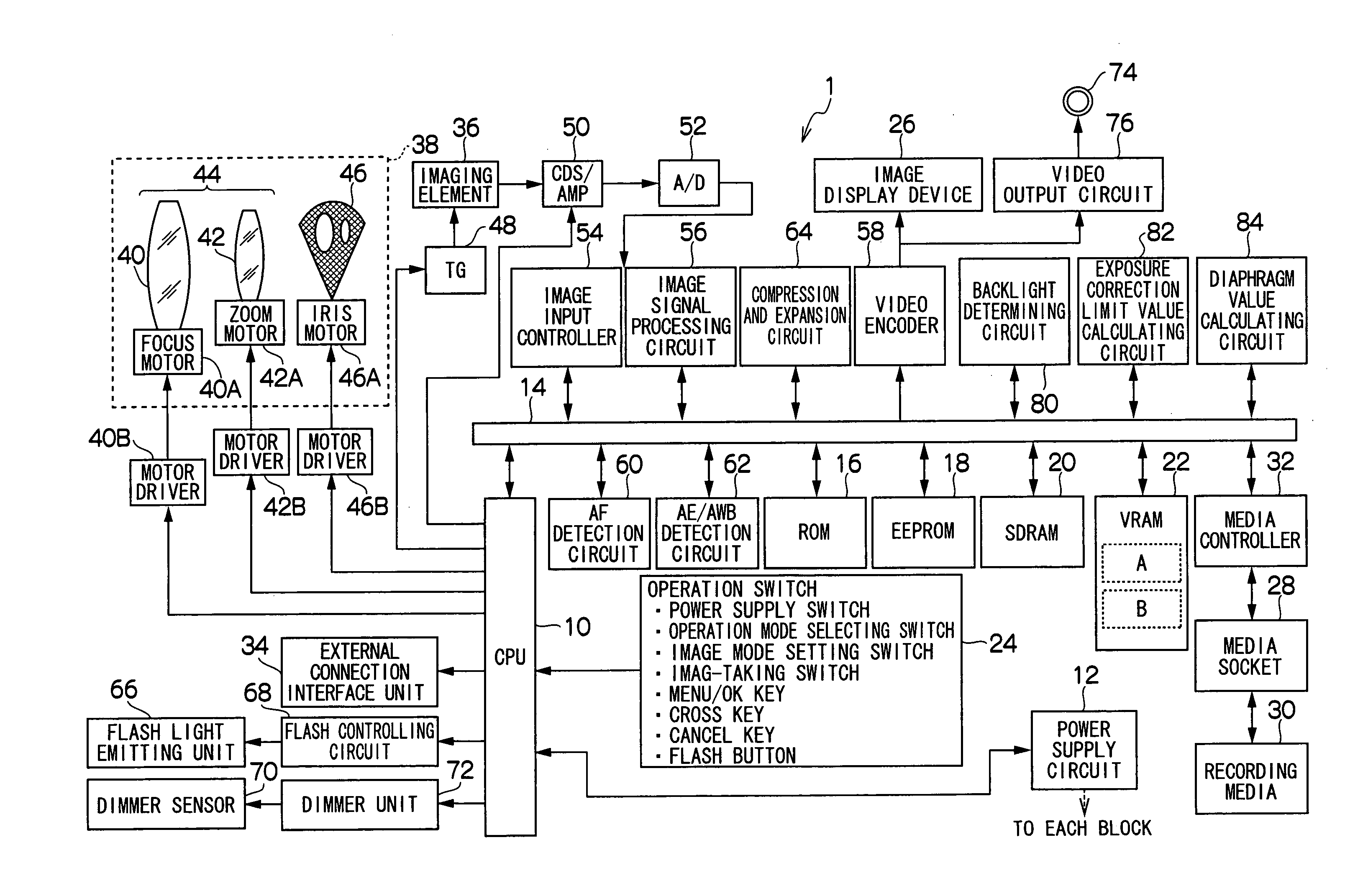
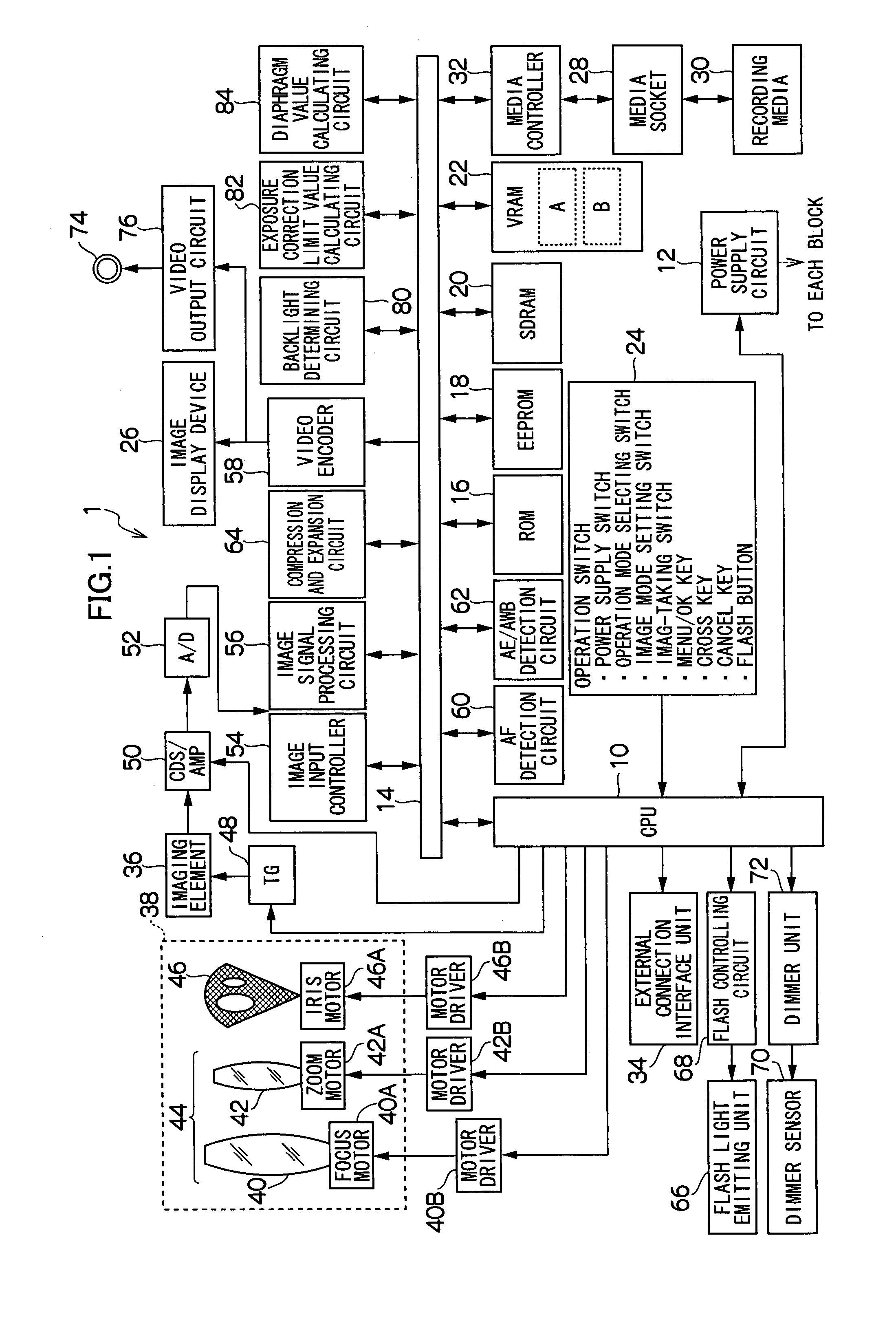
[0108]FIG. 12 is a block diagram illustrating the input and output of the diaphragm value calculating circuit 84 according to the present embodiment. The CPU 10 calculates a distance (object distance) Lobj to a main object based on the focus appraisal value calculated by the AF detecting circuit 60 and inputs the calculated distance to the diaphragm value calculating circuit 84. The diaphragm value calculating circuit 84 provisionally determines a diaphragm value based on the object distance Lobj and imaging sensitivity input from the CPU 10 and outputs the diaphragm value to the CPU 10. If an imaging sensitivity is ISO 100, the provisional determining value of the diaphragm value FNo is expressed by the following equation (5).

GNo=FNo×Lobj  (5)

[0109]The diaphragm value FNo may...


PUM


Abstract

An aspect of the present invention provides an image taking device comprising an image pickup device which picks up an image in a field, a luminance measuring device which divides the image into the predetermined number of blocks to measure the luminance level of each block, a reference average luminance level calculating device which calculates an average luminance level in a predetermined reference area in the image, a bright block sampling device which compares the average luminance level in the reference area with the luminance level of each block to sample a bright block high in luminance level, a backlight determining device which determines whether the picked up image is backlit based on the average luminance level of the bright blocks and the average luminance level of the reference area, and an exposure controlling device which calculates an exposure value based on the result of the determination as to the backlight to control exposure.

Description

BACKGROUND OF THE INVENTION[0001]1. Field of the Invention[0002]The present invention relates to an image taking device and a method of controlling exposure, and in particular, to a technique for controlling exposure at the time of picking up an image.[0003]2. Description of the Related Art[0004]Hitherto, there has been made a proposal that exposure is controlled with reference to the distribution of brightness in a screen (refer to Japanese Patent Application Laid-Open No. 2003-295251). In addition, Japanese Patent Application Laid-Open Nos. 2004-235956 and 2004-341901 disclose a technique in which picked up image is subjected to backlight correction processing.[0005]The technique disclosed in Japanese Patent Application Laid-Open No. 2003-295251 is such that exposure is adjusted to one of a bright and a dark part in the screen. The technique, however, has a problem in that overexposure or underexposure is caused in the entire screen when the area of the bright or the dark part in ...

Claims


Application Information

Patent Timeline
Patent Type & Authority Applications(United States)
IPC IPC(8): H04N5/238H04N5/222G03B7/093G03B7/16G03B7/28G03B15/05H04N5/243
CPCH04N5/2354H04N5/2352H04N23/72H04N23/74
Inventor OKAMOTO, SATOSHI
Owner FUJIFILM CORP
Why Eureka
Try Eureka