Light engine assemblies

a technology of light engine and assembly, which is applied in the direction of fixed installation, lighting and heating equipment, lighting applications, etc., can solve the problems of reducing the life of the lamp and compromising performance, and achieve the effect of excellent heat dissipation

Active Publication Date: 2008-05-15
IDEAL IND LIGHTING LLC
View PDF56 Cites 350 Cited by
  • Summary
  • Abstract
  • Description
  • Claims
  • Application Information

AI Technical Summary

Benefits of technology

[0012]The light engine assemblies according to the present inventive subject matter provide excellent heat dissipation, particularly in the room-side of the device.

Problems solved by technology

Conversely, the dissipation of heat from LEDs and other solid state light emitters within a recessed downlight is very critical.
For instance, if LED junction temperatures are not maintained below manufacturers' ratings, decreased lamp life and compromised performance result.

Method used


Image

  • Light engine assemblies
  • Light engine assemblies
  • Light engine assemblies

Examples


first embodiment

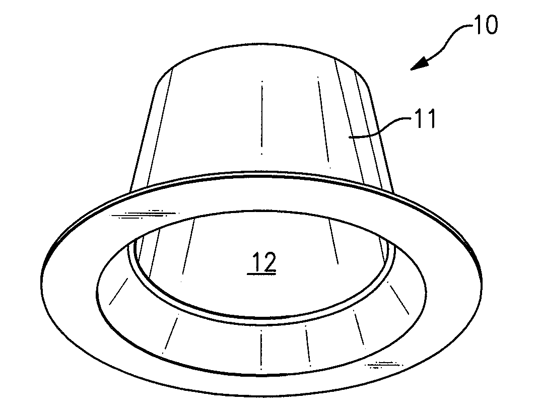
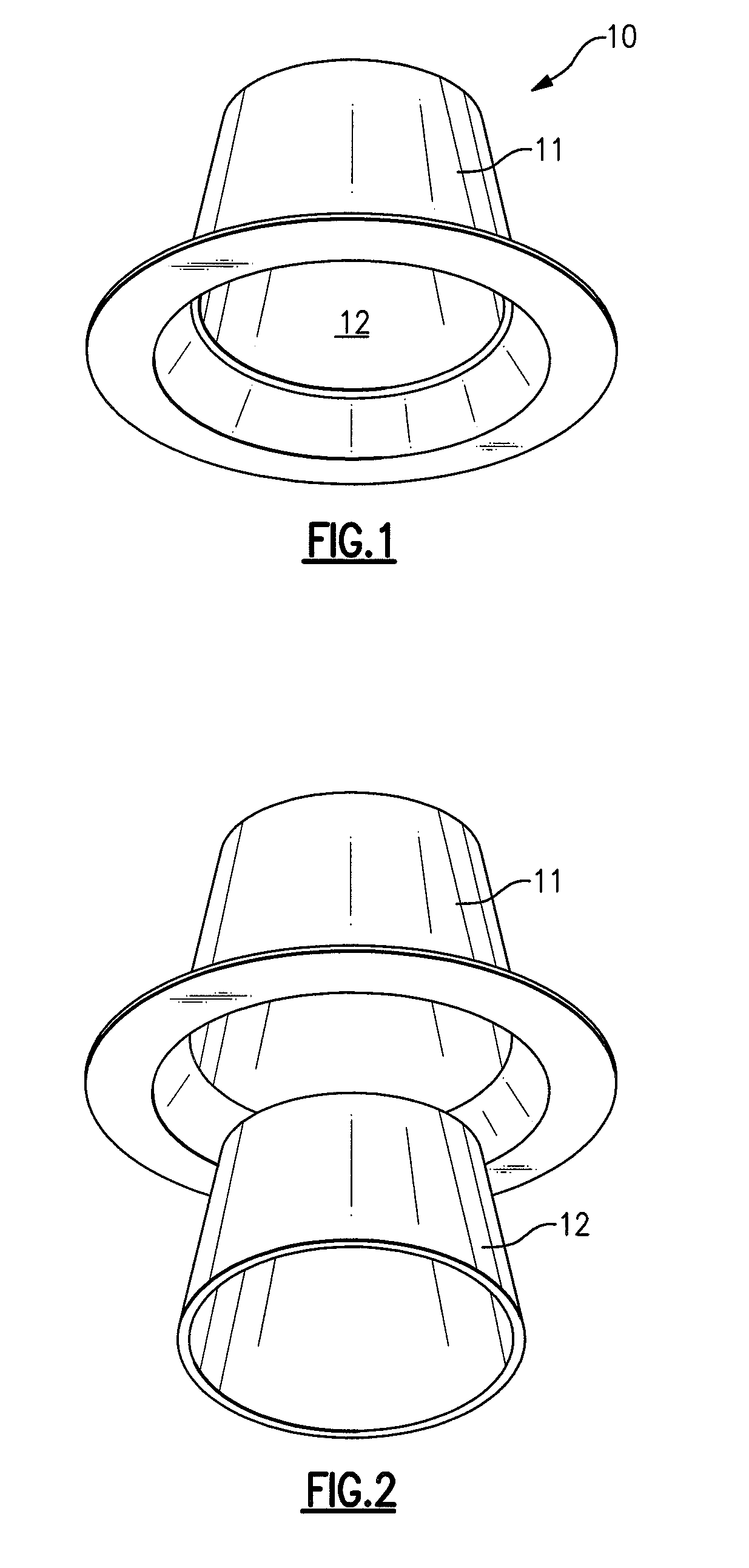
[0175]The first embodiment further comprises a light diffuser 26 positioned within the trim element internal space 14, the trim element 11 and the light diffuser 26 together defining a trim element-diffuser internal space in which the light engine housing 12 is positioned.

[0176]The first embodiment thus provides a light engine housing with smooth sides. The trim element is designed with an upper section profile that creates a very tight force-fit when the light engine housing is installed in the trim element, in order to enable effective heat transfer between the two parts. The trim element may be designed with an open top or an enclosed top that would increase the surface area of conduction. Mechanical fastening (e.g., screws, not shown) between the light engine housing and the trim element can be included in order to provide retention and mating pressure.

[0177]The first embodiment also comprises an electrical connection region which is engageable in an electrical receptacle—in thi...

second embodiment

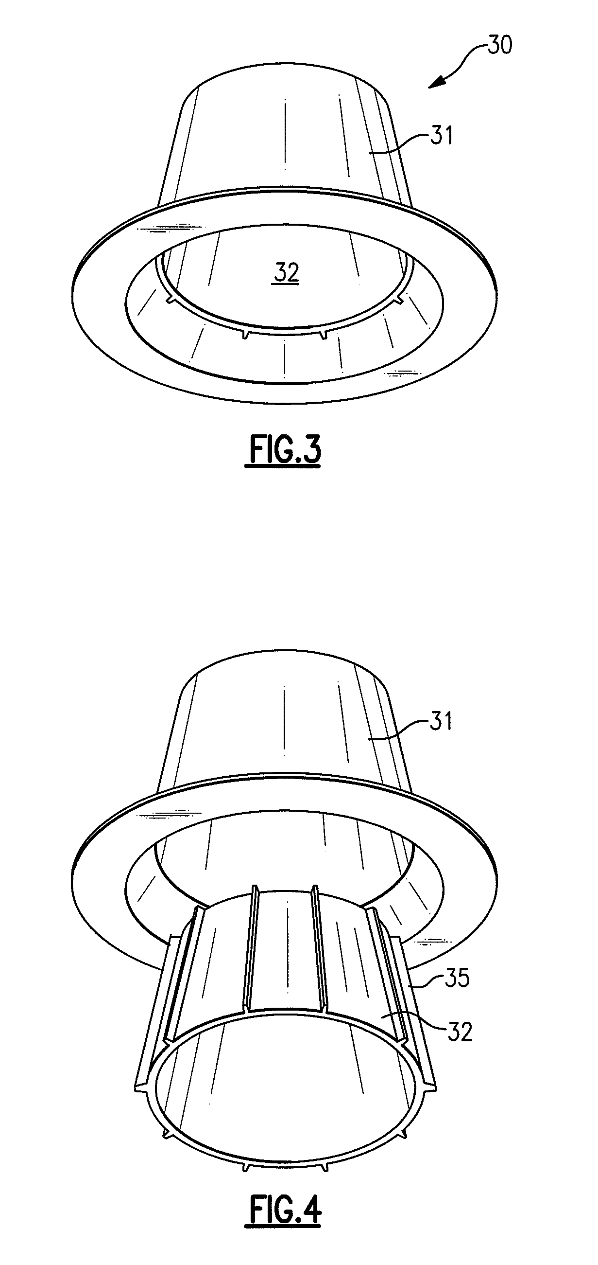
[0179]FIG. 3 is a perspective view of a light engine assembly in accordance with the present inventive subject matter.

[0180]FIG. 12 is a cross-sectional view of the second embodiment depicted in FIG. 3. Referring to FIG. 12, there is shown a light engine assembly 30 comprising a trim element 31, a light engine housing 32, a light engine 35 comprising a plurality of LEDs 33, and a plurality of light engine housing fins 34. In this embodiment, the light engine housing fins 34 are integral with the light engine housing 32 (alternatively, some or all of the fins 34 could be integral with the trim element 31, and / or only some of the fins 34 could be integral with the light engine housing). The trim element 31 defines a trim element internal space 40 in which the light engine housing 32 is positioned. The light engine housing 32 defines a light engine housing internal space 41 in which the light engine 35 is positioned. In this embodiment, each of the light engine housing fins 34 is in co...

third embodiment

[0186]FIG. 7 is a perspective view of a light engine assembly in accordance with the present inventive subject matter.

[0187]FIG. 13 is a cross-sectional view of the third embodiment depicted in FIG. 7. Referring to FIG. 13, there is shown a light engine assembly 70 comprising a trim element 71, a light engine housing 72, a light engine 75 comprising a plurality of LEDs 73, and a plurality of light engine housing fins 74. In this embodiment, the light engine housing fins 74 are integral with the light engine housing 72 (alternatively, some or all of the fins 74 could be integral with the trim element 71, and / or only some of the fins 34 could be integral with the light engine housing). The trim element 71 defines a trim element internal space 76 in which the light engine housing 72 is positioned. The light engine housing 72 defines a light engine housing internal space in which the light engine 75 is positioned. In this embodiment, each of the light engine housing fins 74 is in contac...


PUM


Abstract

A light engine assembly, comprising at least one trim element, a light engine housing, and a light engine comprising at least one solid state light emitter. In some embodiments, an external surface of the light engine housing is in contact with an internal surface of the trim element. In some embodiments, the light engine assembly further comprises at least one thermal interface element positioned between and in contact with the light engine housing and the trim element. In some embodiments, the light engine assembly further comprises light engine housing fins which are in contact with the light engine housing and the trim element.

Description

CROSS-REFERENCE TO RELATED APPLICATIONS[0001]This application claims the benefit of U.S. Provisional Patent Application No. 60 / 858,881, filed Nov. 14, 2006, the entirety of which is incorporated herein by reference.FIELD OF THE INVENTION(S)[0002]The present inventive subject matter relates to light engine assemblies for use in lighting devices, and lighting devices which include such light engine assemblies. In some embodiments, the present inventive subject matter relates to light engine assemblies which include solid state light emitters, for example, light emitting diodes.BACKGROUND OF THE INVENTION(S)[0003]A large proportion (some estimates are as high as twenty-five percent) of the electricity generated in the United States each year goes to lighting. Accordingly, there is an ongoing need to provide lighting which is more energy-efficient. It is well-known that incandescent light bulbs are very energy-inefficient light sources—about ninety percent of the electricity they consum...

Claims


Application Information

Patent Timeline
Patent Type & Authority Applications(United States)
IPC IPC(8): F21V7/00F21K99/00
CPCF21S8/026F21S48/328F21V15/01F21Y2105/001F21V29/2212F21W2131/401F21Y2101/02F21V29/004F21Y2105/10F21Y2115/10F21S45/47F21V29/75F21S41/50
Inventor PICKARD, PAUL KENNETHTROTT, GARY DAVID
Owner IDEAL IND LIGHTING LLC
Why Eureka
Try Eureka