
Preforms for Creating Decorative Fused Glass

a technology forms, which is applied in the field of decorative fused glass objects, can solve the problems of high stress and fragmentation, difficult for novice or even experienced glass craftsmen to obtain the results they plan, and high risk of cutting glass and working with cut glass, so as to achieve the effect of predictability

Inactive Publication Date: 2008-05-22
KERNAN MELVIN CRAIG
View PDF0 Cites 10 Cited by
  • Summary
  • Abstract
  • Description
  • Claims
  • Application Information

AI Technical Summary

Benefits of technology

[0032](l) Make it easy to create multiple fused glass objects with the same pattern, for example to create a matching set of fused glass windows, glass dishes or decorative glass tiles.
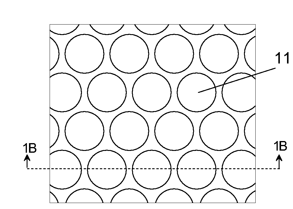
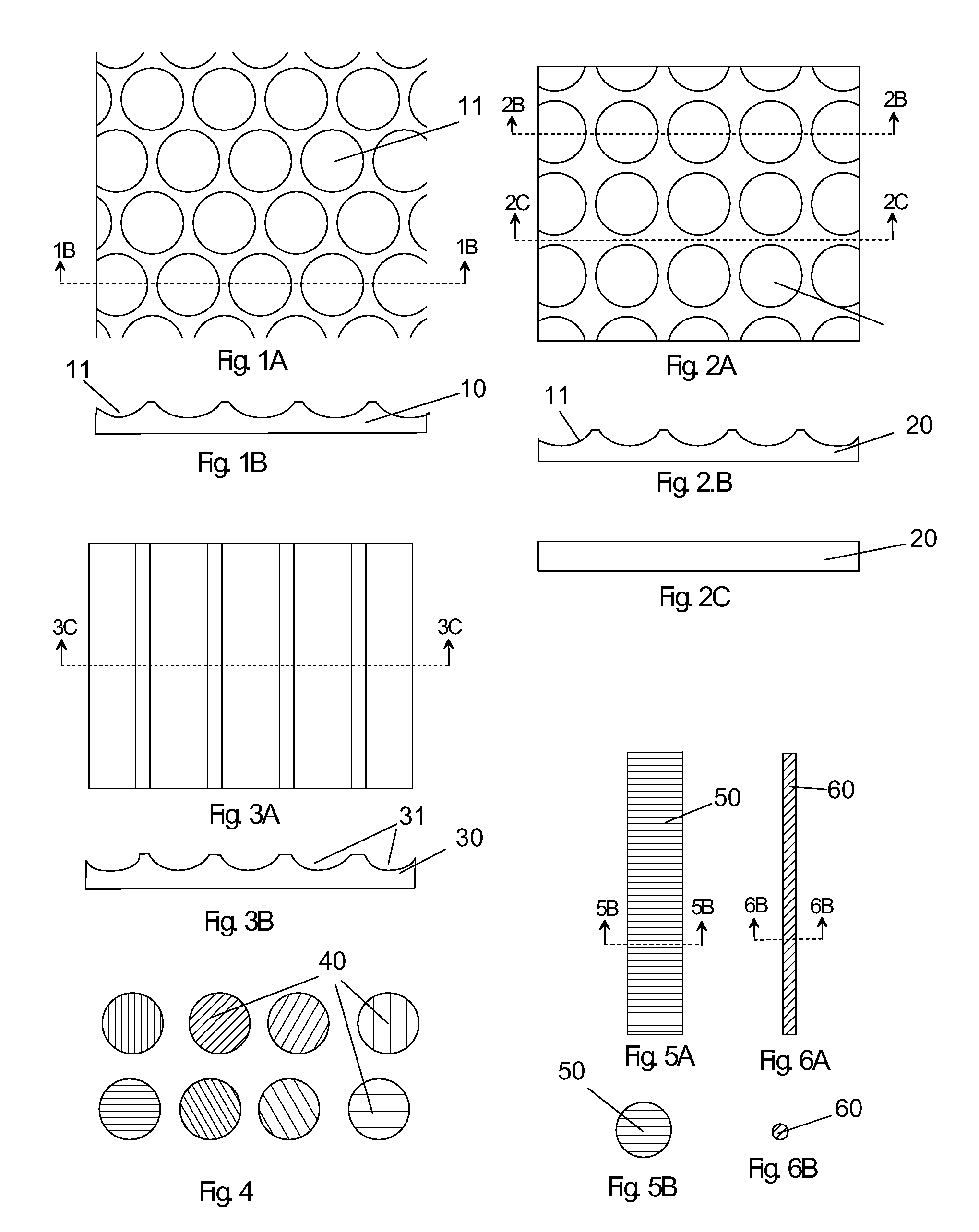
[0033]In the drawings, closely related figures have the same number but different alphabetic suffixes. FIGS. 1A through 6B show glass preforms or portions of glass preforms used in the preferred embodiment. FIGS. 7A through 16 illustrate some ways of using the preferred embodiment preforms to create decorative fused glass objects or parts thereof. FIGS. 17 to 28 illustrate other embodiments. FIGS. 29A to 31 illustrate a two layer layout sheet embodiment for planning and layout of fused gla

Problems solved by technology

Using glass components with insufficiently matched COE can result in high level of stress and pieces that fracture when cooling or are handled.
This makes it difficult for novice or even experienced glass craftsmen to obtain the results they plan.
(b) Cutting glass and working with cut glass requires care and involves an element of danger.
Cut and broken glass pieces have sharp edges that can cause serious cuts.
Working with frit and cutting glass present the additional danger from small airborne particle that can cause lung and eye damage.
This, however, introduces additional layout steps and makes it difficult to change layout or correct an error.
(d) The infinite variety of potential cut glass shapes, the infinite possible arrangement of the pieces, and the dependence of the result on the temperature profile used in fusing the glass make it extremely difficult to produce CAD (computer aided design) software to aid in the design of fused glass objects.
(e) Producing fused glass objects having regular mosaic patterns is difficult and time consuming because it requires precision cutting and placing of many glass pieces.
(f) For other than very simple designs making multiple fused objects with the same design is difficult and labor intensive.
Making accurate multiple copies of complex fused glass designs is almost impossible.
(g) The variety of shaped pieces used in making fused glass objects make it difficult to assemble fused glass arrangements with robotic tools.
Robotic equipment to cut even relatively simple shapes is very expensive.
Designing robotic systems to manipulate a wide variety of shapes is very difficult.

Method used


Image

  • Preforms for Creating Decorative Fused Glass
  • Preforms for Creating Decorative Fused Glass
  • Preforms for Creating Decorative Fused Glass

Examples


example 1.1

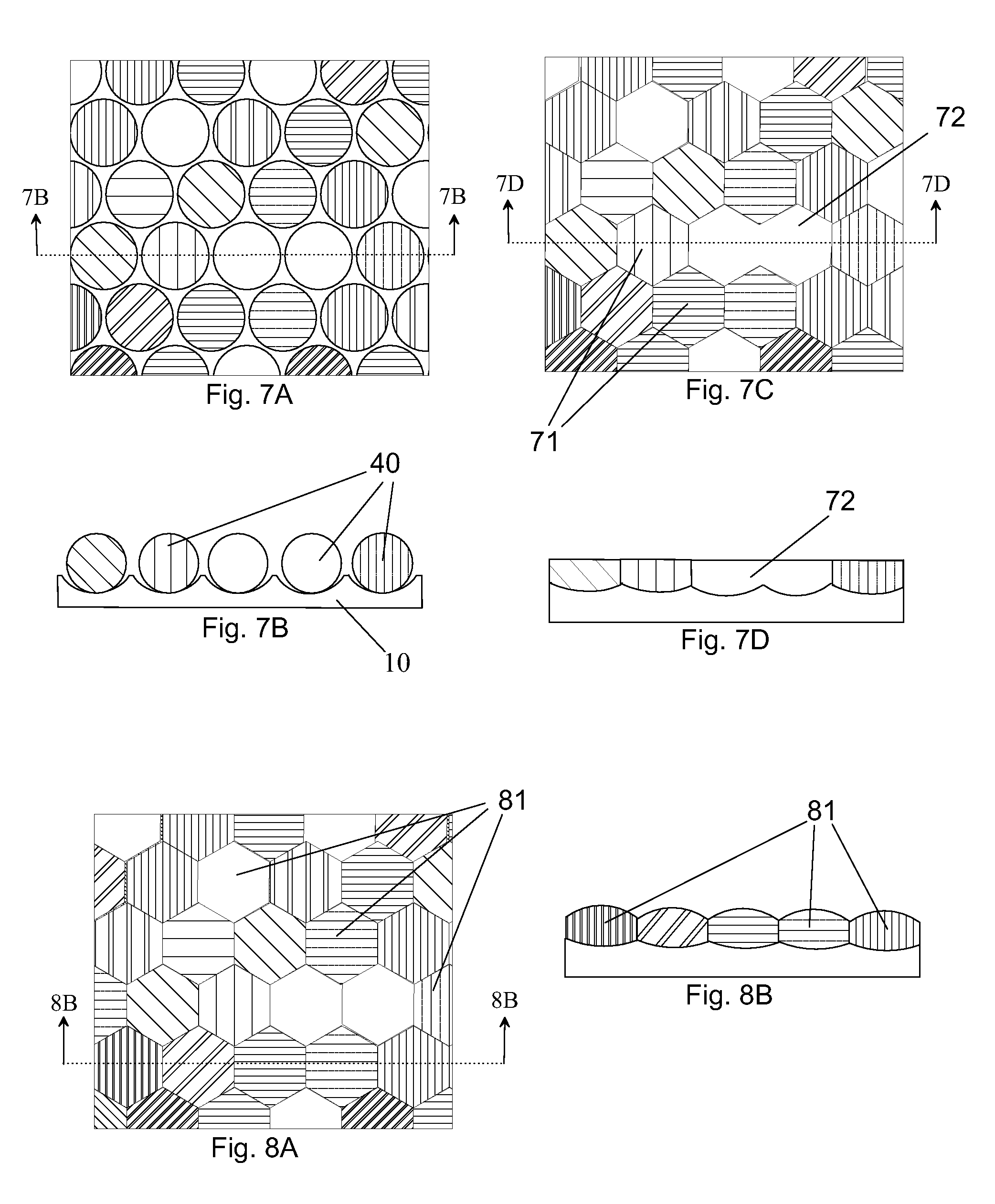
Using a Hexagonal Grid Base Sheet and Ball Preforms to Create a Fused Glass Object having a Mosaic Pattern of Small Hexagons. (FIGS. 7A Through 7D)

[0076]The preforms are used in the following way:

[0077]The ball preforms 40 are placed in the indentations of the hexagonal grid base sheet 10 in the color arrangement desired in the fused glass mosaic object to be made. FIGS. 7A and 7B shows a part of such an arrangement. The placement of colors could be planned with design sheets, planned with computer graphics, or inspired as the balls are placed.

[0078]The combination of the hexagonal base sheet and ball preforms as arranged above is heated in a kiln to fuse all these preforms together into a single relatively flat decorative glass object (FIG. 7D). As glass balls melt they are deformed by gravity and spread out to meet one another forming a mosaic of hexagons 71. Note that neighboring elements of the same color fuse together seamlessly into a single element 72. The ball preforms fuse ...

example 1.2

Using a Hexagonal Grid Base Sheet and Ball Preforms to Create a Fused Glass Object Having a Mosaic Pattern of Hexagonal Lenses. (FIGS. 7A, 7B, 8A and 8B)

[0081]Using the same preforms proceed as in example 1.1 above except using somewhat less heating (lower peak temperature or shorter duration at high temperature) in the kiln. The balls when heated somewhat less do not flatten out completely but retain a domed form 81 (FIGS. 8A and 8B) that refracts light in the manner of a small colored lens.

[0082]When viewing a scene through such a fused glass object each small lens shows a miniature inverted image of the scene colored by the color of the glass. The resulting array of small images colored by the various glass elements can be quite striking[0083]Note that the combination of gravity and surface tension effects will shape a variety of raised forms into rounded domed structures. Thus, the ball preforms 40 need not be spherical. For glass objects less than about 10 mm surface tension ef...

example application 1.3

Using a Rectangular Grid Base Sheet 20 and Ball Preforms 40 to Create a Fused Glass Object Having a Pattern of Square Elements. (FIGS. 9A Through 9D)

[0084]FIGS. 9A and 9B show a sections of a rectangular grid preform 20 having all the indentations filled with ball preforms 40. When this arrangement is fused into a glass object it will have a mosaic pattern of square elements 91 shown in FIGS. 9C and 9D. The square elements in the mosaic could be either flat or domed forming lenses depending on the temperature profile used in fusing.

[0085]Since adjacent ball preforms of the same color fuse together seamlessly, grouping ball preforms of the same color together in the layout results in larger mosaic elements.


PUM

PropertyMeasurementUnit
Coloraaaaaaaaaa
Sizeaaaaaaaaaa
Shapeaaaaaaaaaa

Abstract

Coordinated preforms made of COE (coefficient of expansion) compatible glass are shaped for making predictable decorative patterns in fused glass. When color design preforms 40, 50, 60 are positioned using the indentations 11, 31 in base sheet preforms 10, 20, 30 they will deform into predictable mosaic patterns when the arrangement is fused together.

Description

CROSS-REFERENCE TO RELATED APPLICATIONS [0001]Not ApplicableFEDERALLY SPONSORED RESEARCH [0002]Not ApplicableSEQUENCE LISTING OF PROGRAM [0003]Not ApplicableFIELD OF INVENTION[0004]This invention relates to making fused glass objects used as decorative art, architectural glass, wall tiles, and objects to be further processed into stained glass or slumped glass objects.BACKGROUND OF THE INVENTION[0005]Artistic and decorative glass objects can be made by fusing (melting together) glass pieces of various colors. To make such decorative objects pieces of glass are placed together, often overlapping, and fused into a single usually relatively flat glass object in a kiln.[0006]Glass fused into such decorative objects can be used as stand alone artistic pieces, elements of stained glass objects such as church windows or glass lamp shades, architectural tiles and other objects. After fusing the resulting glass object are sometimes slumped (heated to softening and shaped by gravity) into a s...

Claims


Application Information

Patent Timeline
IPC IPC(8): C03B23/20
CPCB44C3/123B44C5/00C03B23/20C03B23/0026B44C5/0407
Inventor KERNAN, MELVIN CRAIG
Owner KERNAN MELVIN CRAIG
Learn More