Method and Materials for Improving Evaporative Heat Exchangers

a heat exchanger and evaporative technology, applied in the direction of trickle coolers, free-cooling systems, combustion air/fuel air treatment, etc., can solve the problems of limiting the degree of cooling available, limiting the use of this cooling method, and construction suffering a number of deficiencies

Inactive Publication Date: 2008-05-22
F F SEELEY NOMINEES
View PDF16 Cites 15 Cited by
  • Summary
  • Abstract
  • Description
  • Claims
  • Application Information

AI Technical Summary

Benefits of technology

[0031]The inventive aspects of the present invention when combined can result in an indirect evaporative cooler which fully utilises the characteristics of corrugated media to produce a compact, efficient and economical cooler. Such an indirect evaporative air cooler typically comprises a fan means for the delivery of air, an indirect evaporative heat exchanger and an air delivery means including an airflow resistance means.

Problems solved by technology

This limitation in achievable temperature and the addition of moisture to the air severely limits the degree of cooling available by this method, as well as limiting the use of this means of cooling to relatively hot, dry climates.
However, the construction suffers a number of deficiencies.
Heat transfer between the wet and dry air passages is inefficient due to the air boundary layers at both sides of the medium between the passages, requiring large surface areas for effective transfer of heat.
The available delivered airflow for a given size of heat exchanger is therefore low, resulting in an unacceptably large and costly construction for practical airflows.
There are also considerable practical difficulties with the construction and operation of such an indirect evaporative cooler.
Manifolding of air streams to the respective wet and dry ducts requires individual separation of the ducts with laborious and expensive sealing systems.
When used with normal potable water supplies, water evaporated from the wet duct leaves behind salts, which cannot be easily removed, eventually clogging the heat exchanger.
The interaction of air streams within the adjacent corrugations in this construction of wetted media results in intense evaporation from the wet surfaces and intense heat transfer from the cold surfaces formed as a result of that evaporation.

Method used


Image

  • Method and Materials for Improving Evaporative Heat Exchangers
  • Method and Materials for Improving Evaporative Heat Exchangers
  • Method and Materials for Improving Evaporative Heat Exchangers

Examples


Embodiment Construction

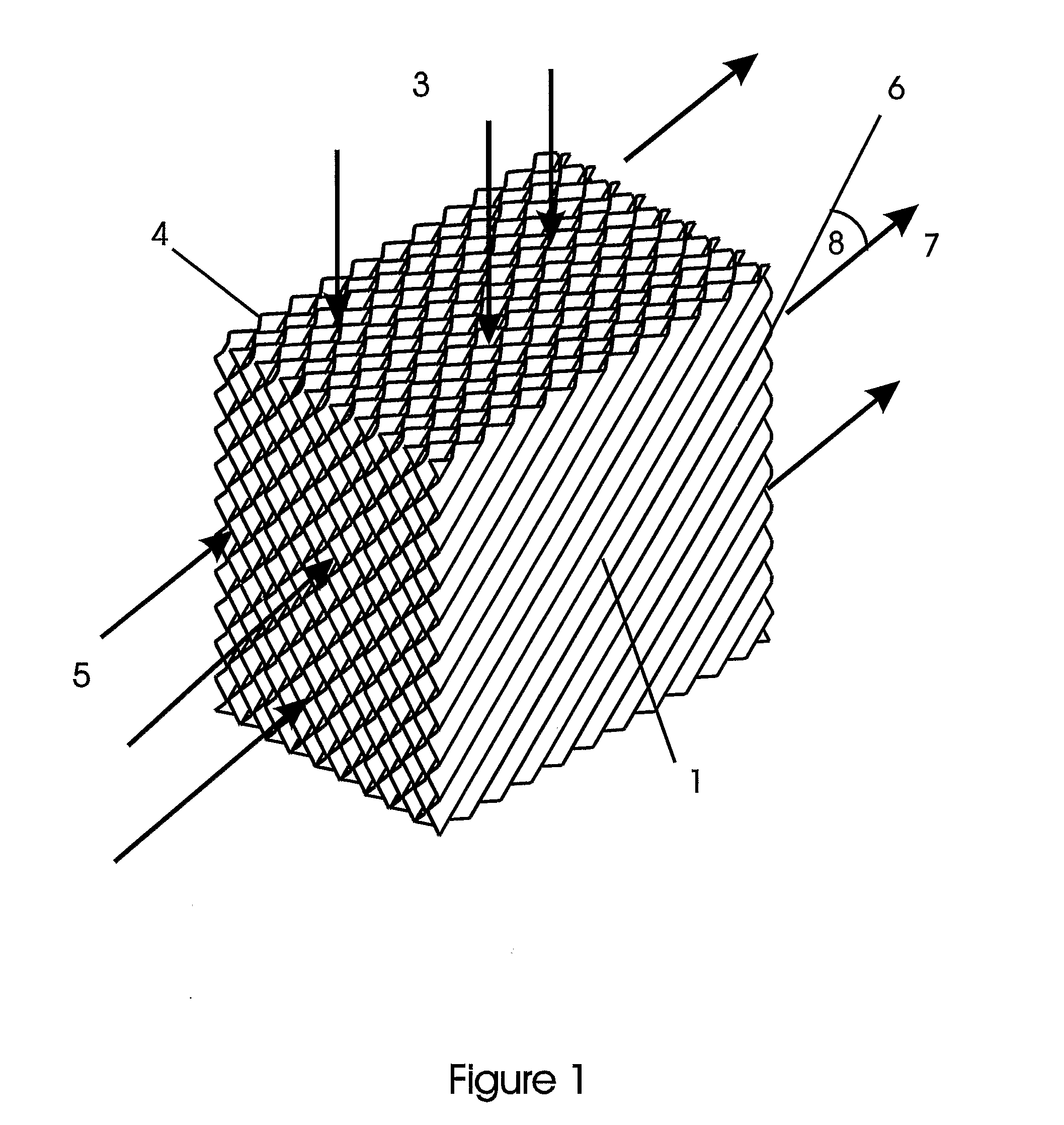
[0041]In FIG. 1, the prior art corrugated media is shown as a block of sheets of corrugated, wettable media within which dry air and water on the wetted surfaces interact. The block 1 is constructed from individual sheets 4 of corrugated media (typically treated paper of a type which readily wicks water along its surface). Individual corrugations 6 are impressed in the media during manufacture and the sheets arranged such that the corrugations are set at an angle 8 to the edges of the block of media. Adjacent sheets 4 are typically glued together with reversed corrugation angles creating complex air and water passages within the matrix of the block.

[0042]In operation, water is introduced in the direction 3 and applied to the top surface of the block of media. As the water 3 descends through the matrix, it encounters numerous points within the matrix where the corrugations 6 of adjacent sheets 4 meet. At each of these intersection points, part of the water is directed one way around ...


PUM

PropertyMeasurementUnit
Temperatureaaaaaaaaaa

Abstract

A corrugated laminate material (44) for use in an evaporative heat exchanger, said material including a water retaining medium having a wettable surface (40) and an opposed vapour resistant surface (42).

Description

FIELD OF THE INVENTION[0001]The present invention relates to improvements in heat exchange capacity of evaporative heat exchangers. In particular, one aspect of this invention relates to a material suited to use in forming heat exchange surfaces of evaporative heat exchangers. Additional inventions are disclosed that relate to the operation of evaporative coolers. For ease of understanding, the aspects of this invention will be described in connection with the heat exchange core of counter flow evaporative coolers, as well as to methods, equipment and systems for the ventilation and cooling of enclosed spaces. The various aspects of this invention can be applied to self-contained air conditioning units suitable for supplying cooled air to an enclosed space, and to self-contained conditioning units suitable for supplying cooled water for use in heat exchange units forming part of a system for the cooling of enclosed spaces.DESCRIPTION OF THE PRIOR ART[0002]Throughout this description...

Claims


Application Information

Patent Timeline
Patent Type & Authority Applications(United States)
IPC IPC(8): B32B3/28F28F25/00F24F6/00F24F3/14F24F1/0059
CPCB32B3/28Y10T156/1002B32B29/06B32B29/08B32B2250/02B32B2255/12B32B2307/554B32B2307/7246B32B2307/7265B32B2597/00F24F5/0035F24F2001/0092F28D5/02F28F25/087Y02B30/545Y10T156/10B32B25/10F24F1/0007Y02B30/54F24F1/0059
Inventor JAMES, ROBERT WILTON
Owner F F SEELEY NOMINEES
Why Eureka
Try Eureka