Large holesaw mandrel assembly

a mandrel and assembly technology, applied in the field of mandrels, can solve the problems of large spring force that cannot be utilized, vibration and noise of the holesaw, etc., and achieve the effect of enhancing connection and preventing vibration and play

Active Publication Date: 2008-05-22
BLACK & DECKER INC
View PDF38 Cites 17 Cited by
  • Summary
  • Abstract
  • Description
  • Claims
  • Application Information

AI Technical Summary

Benefits of technology

[0006]The present disclosure overcomes the deficiencies of the prior art. The present disclosure provides a resilient member which compresses when contact by the holesaw to eliminate play between the holesaw and the mandrel body when the holesaw is in a used position. The present disclosure provides a magnetized sliding collar which is magnetically attracted to the mandrel body to enhance the connection between the sliding collar and the mandrel body to prevent withdrawal of the pins from apertures in the holesaw. The present disclosure provides a positioning member in the pilot drill bore to provide a desired orientation of the pilot drill bit.
[0007]According to a first aspect of the disclosure, a holesaw mandrel assembly comprises a mandrel including a body having at least one bore. A first end couples the body with a driver, such as a drill motor. A second end extends from the body and includes a threaded spud. A sliding collar is axially movable on the body. The sliding collar includes at least one pin extending through the mandrel body at least one bore into a holesaw. A resilient member is adjacent the threaded spud. The resilient member compresses when it is contacted by a holesaw screwed onto the threaded member. The resilient member eliminates play between the holesaw and the mandrel body when in a used position. The resilient member may be an O-ring surrounding the threaded spud. The O-ring abuts and rests upon the mandrel body.
[0008]According to a second aspect of the disclosure, a holesaw mandrel assembly comprises a mandrel including a body having at least one bore and a first end coupled with the body. The first end is coupled with a driver, such as a drill motor. A second end extends from the body and includes a threaded spud. A sliding collar is axially movable on the body. The sliding collar includes at least one pin extending through the mandrel body at least one bore to couple with a holesaw. The sliding collar is magnetized such that it is magnetically attracted to the mandrel body. This enhances the connection between the sliding collar and the mandrel body to prevent withdrawal of the at least one pin from the holesaw. One or more magnets can be inlayed and coupled with the sliding collar. The one or more magnets may be equally spaced about the sliding collar.

Problems solved by technology

Thus, there is vibration and noise associated with the holesaw during use.
Also, since the pins, which are attached to a spring loaded sliding collar, must be removed from the holesaw through the mandrel body in order to remove the holesaw, a large spring force cannot be utilized.

Method used


Image

  • Large holesaw mandrel assembly
  • Large holesaw mandrel assembly
  • Large holesaw mandrel assembly

Examples


Embodiment Construction

[0016]The following description is merely exemplary in nature and is not intended to limit the present disclosure, application, or uses.

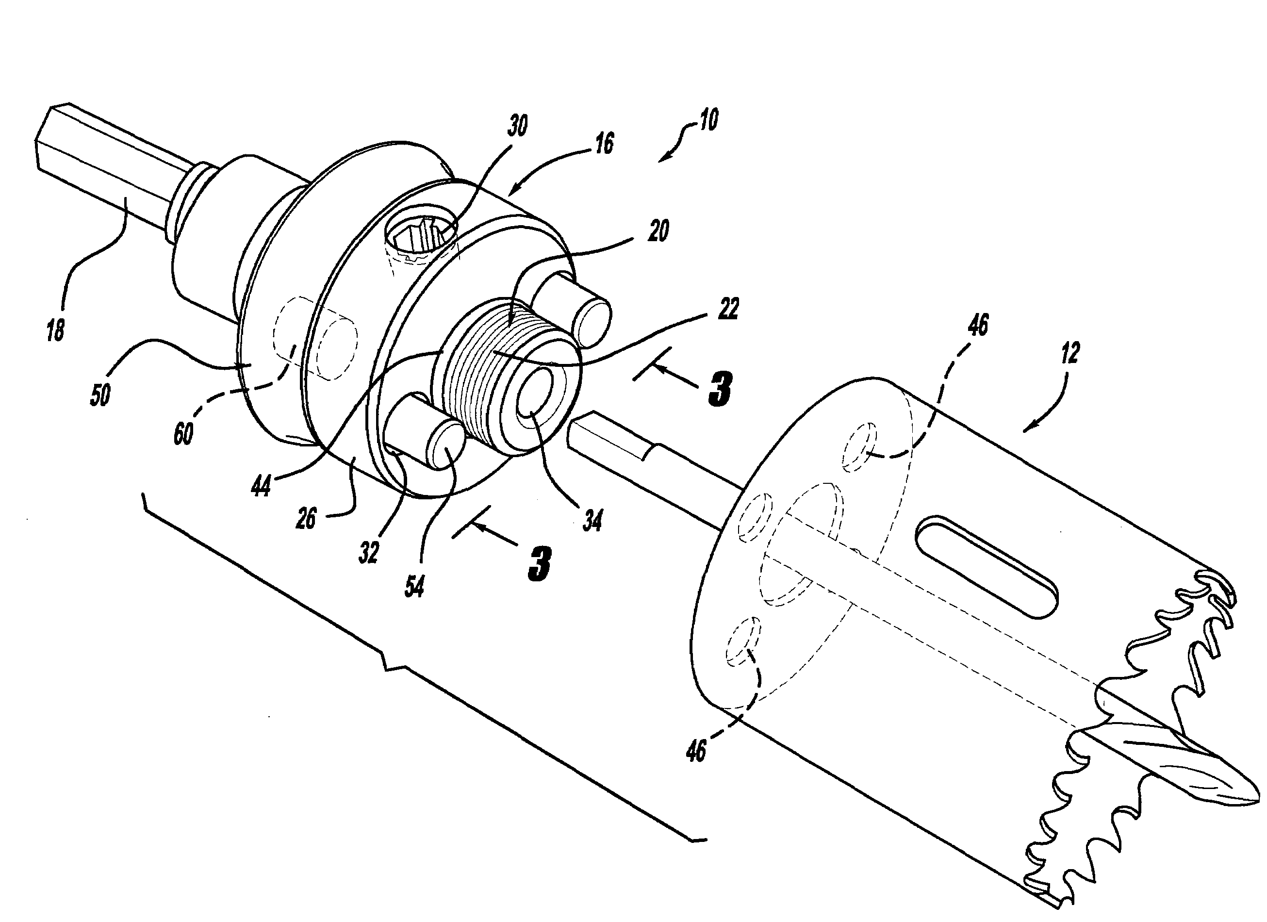
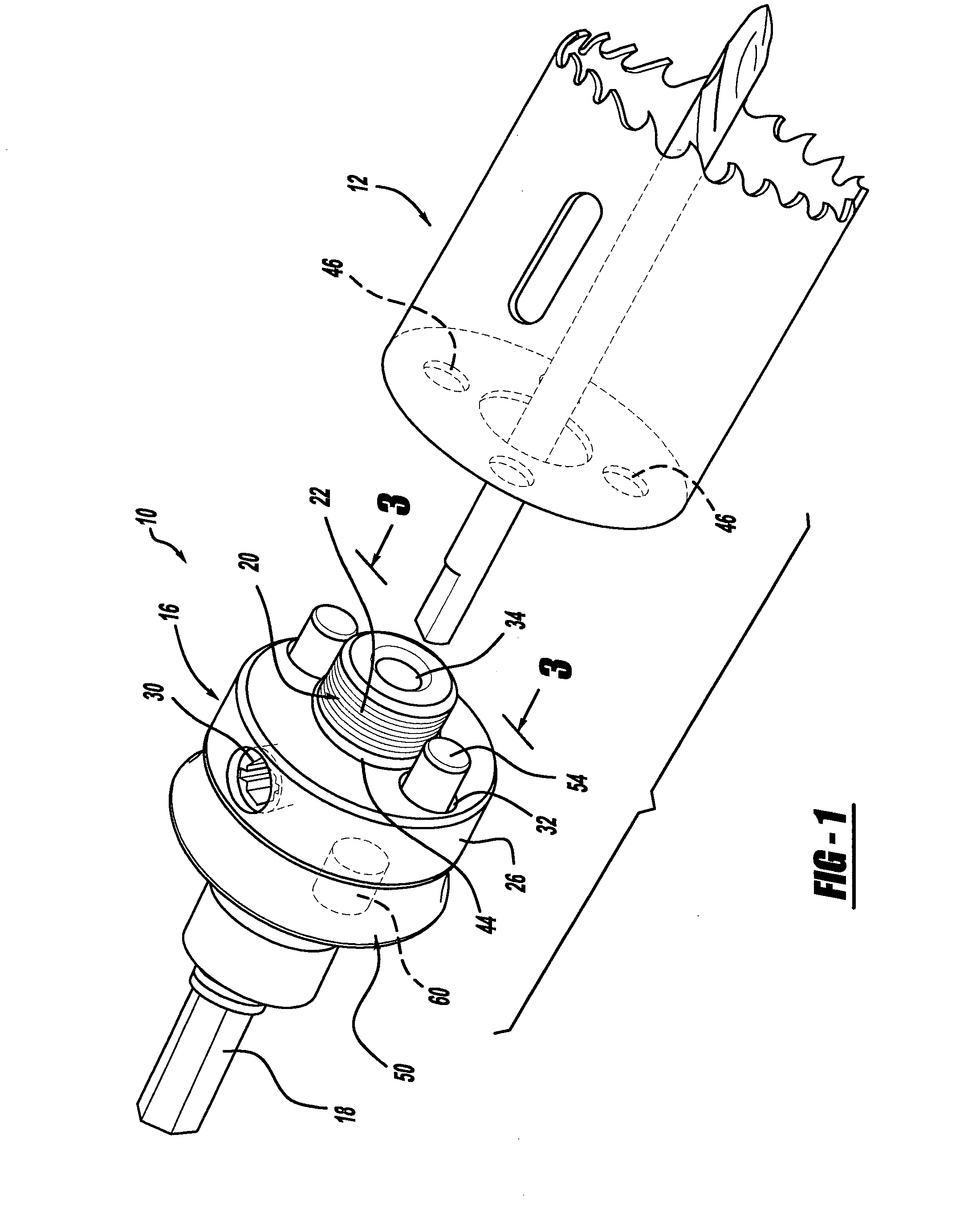
[0017]Turning to the drawings, a holesaw mandrel assembly is illustrated and designated with the reference numeral 10. A holesaw 12 is illustrated in perspective. Also, a pilot drill bit extends from the mandrel assembly 10.

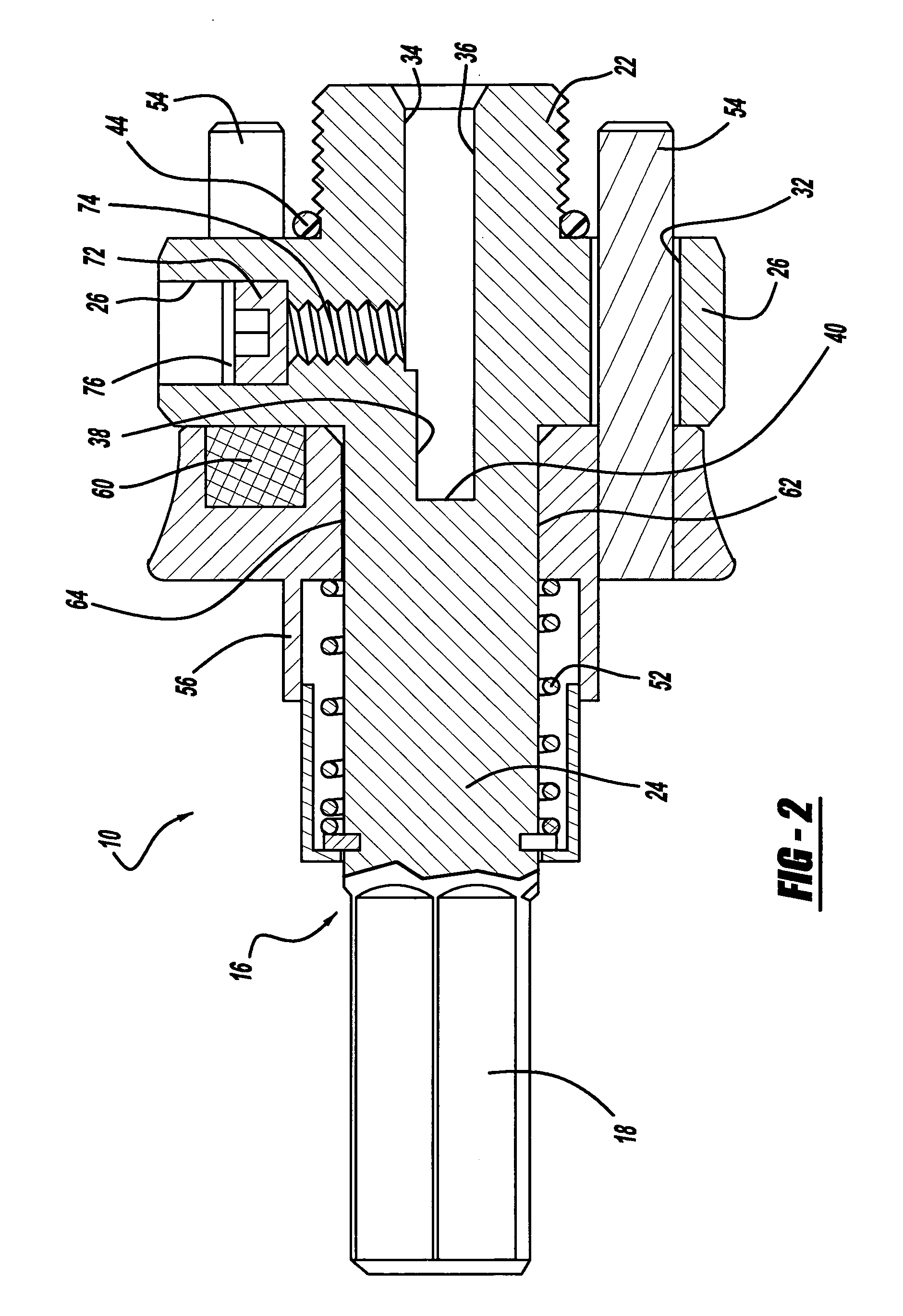
[0018]The mandrel assembly 10 includes a mandrel body 16. The mandrel body 16 includes a first end 18 and a second end 20. The first end 18 may have an outer polygonal shape to fit into a driver such as a drill motor. The second end 20 includes a threaded spud 22. The threaded spud 22 receives the holesaw 12 in a conventional manner.

[0019]The mandrel body 16 has an enlarged cylindrical portion 24 adjacent the first end 18. The enlarged cylindrical portion 24 terminates at a cylindrical collar 26. The cylindrical collar 26 includes a set screw bore 28 which receives set screw 30. Also, bores 32 extend through the cylindrical colla...


PUM

PropertyMeasurementUnit
resilientaaaaaaaaaa
spring forceaaaaaaaaaa
shapeaaaaaaaaaa

Abstract

A holesaw mandrel has a mandrel body with at least one bore, a pilot drill bit bore, and a first end coupled with the body. The first end is coupled with a driver. A second end extends from the body and includes a threaded spud. A sliding collar is axially movable on the mandrel body. The sliding collar includes at least one pin extending the bore in the mandrel body. A resilient member is positioned adjacent the threaded member to provide enhanced securement of the holesaw. The sliding collar is magnetized to prevent withdrawal of the pin from the holesaw. A positioning member is in the pilot drill bore to provide a desired orientation of the pilot drill bit.

Description

FIELD[0001]The present disclosure relates to holesaws and, more particularly, to a mandrel assembly which enables easy removal of a holesaw.BACKGROUND[0002]Holesaw mandrel assemblies exist in the art. Ordinarily, the holesaw mandrel assembly includes a threaded spud to receive a holesaw. The mandrel assembly also includes pins which fit into apertures in the holesaw base to maintain the holesaw in position during use. When the holesaw is in a use position, ordinarily the holesaw is loose on or has play between the pins enabling slight movement of the holesaws. This is due to the fact that the apertures in the base of the holesaw do not align with the pins when the holesaw is tightened onto the mandrel. Thus, the holesaw must be backed off from contacting the mandrel in order for the pins to fit into the apertures in the base of the holesaw. Thus, there is vibration and noise associated with the holesaw during use.[0003]Also, during use, since there is play between the holesaw and th...

Claims


Application Information

Patent Timeline
Patent Type & Authority Applications(United States)
IPC IPC(8): B23B31/113B23B51/04
CPCB23B31/008B23B31/1075B23B31/11B23B51/0426B23B51/0473Y10T279/3418B23B2260/136B23B2270/38Y10T408/895Y10T408/95B23B2251/70
Inventor BRUNSON, MARK E.
Owner BLACK & DECKER INC
Why Eureka
Try Eureka