
Tibia impacter

a technology of tibia and shin bone, which is applied in the field of tibia impactor, can solve the problems of difficulty in accurately maintaining the level condition, and achieve the effect of improving the level condition

Inactive Publication Date: 2008-05-22
SEO JAI GON +1
View PDF13 Cites 31 Cited by
  • Summary
  • Abstract
  • Description
  • Claims
  • Application Information

AI Technical Summary

Benefits of technology

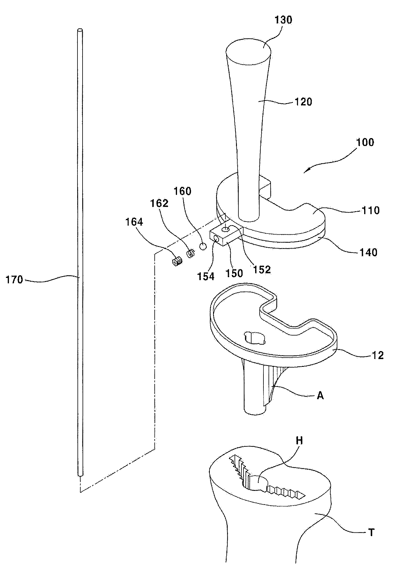
[0010]Accordingly, it is an object of the present invention to provide a tibia impacter having an alignable function by making the striking axis of tibia impacter coincide with the central axis of the artificial tibia implant and by vertically installing on one side of the tibia impacter a guide bar that helps to attain a level position of the artificial tibia implant through the mechanical axis of the tibia.
[0011]In accordance with the present invention, there is provided a tibia impacter having a body, a striking portion formed at the top end of the body, and a pressing portion formed at the bottom end of the body, which presses an artificial tibia implant through the pressing portion when the striking portion is pressed, so as to help the artificial tibia implant be mounted on the top surface of the cut tibia, the tibia impacter comprising: a guide bar which is installed vertically on one side of the tibia impacter for comparison with the mechanical axis of the tibia to compare the mechanical axis of the tibia and the guide bar, so that the level condition of the artificial tibia implant mounted on the top surface of tibia can be confirmed.

Problems solved by technology

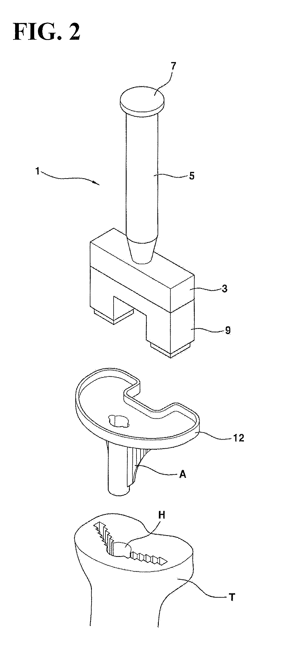
However, the conventional tibia impacter 1 composed like above has a problem that it is difficult to maintain the level condition accurately because the level condition is attained by adjusting the striking strength while confirming the thickness of bone cement with the naked eye only.
Another problem is that because the central axis A of the artificial tibia implant 12 (i.e., the mechanical axis of tibia T) and the striking axis of the tibia impacter 1 are not on the same axis line but are eccentric, the artificial tibia implant 12 is installed inclined forward or backward even by a slight difference of striking force, as shown in FIG. 3.

Method used


Image

  • Tibia impacter
  • Tibia impacter
  • Tibia impacter

Examples


Embodiment Construction

[0021]Below will be described in detail the present invention with reference to the accompanying drawings. And in the description below, the elements that are identical with those of the conventional structure are shown with identical symbols and duplicated description is omitted for simplification.

[0022]Referring to FIG. 4 to FIG. 6, a tibia impacter 100 according to the present invention is provided with a body 110, on the top surface of which is formed a vertically extended handle portion 120, wherein at the top end of the handle portion 120 is monolithically formed a striking portion 130, and at the bottom end of the body 110 is monolithically formed a pressing portion 140. Here, it is preferable that the body 110, handle portion 120 and striking portion 130 are made of metal or aluminum material so as to maintain strength when impact is applied, and the pressing portion 140 is made of synthetic resin material so as not to damage the surface of the artificial tibia implant 12. A...


PUM


Abstract

The present invention discloses a tibia impacter provided with an alignment guide function that helps an artificial tibia implant to be adjusted to the level condition when bone cement is applied to the top surface of the cut tibia and an artificial tibia implant is driven in and fixed. The tibia impacter comprises a guide bar which is installed vertically on one side of the tibia impacter for comparison with the mechanical axis of the tibia to compare the mechanical axis of the tibia and the guide bar, so that the level condition of the artificial tibia implant mounted on the top surface of tibia can be confirmed.

Description

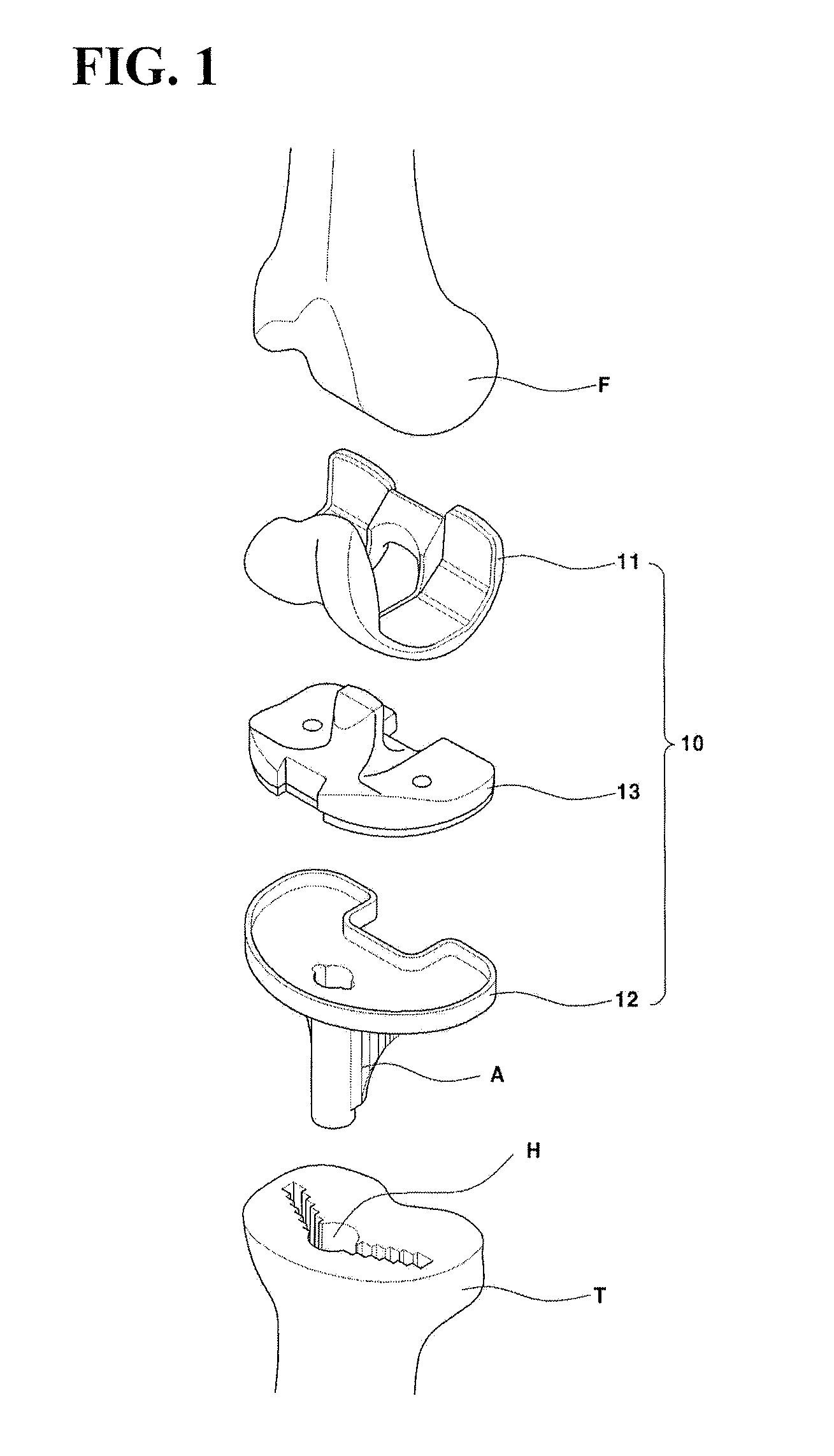
[0001]This application claims priority to Korean Patent Application No. 2006-00000, filed on Nov. 0, 2006, in the Korean Intellectual Property Office, the entire contents of which are hereby incorporated by reference.BACKGROUND OF THE INVENTION[0002]1. Field of the Invention[0003]The present invention relates to a tibia impacter, and more specifically to a tibia impacter provided with an alignment guide function that helps an artificial tibia implant to be adjusted to a level condition when bone cement is applied to the top surface of the cut tibia and the artificial tibia implant is driven and fixed into the top end of the cut tibia.[0004]2. Description of the Related Art[0005]As is well known, artificial knee joint substitution surgery, in which the knee joint that is damaged or deformed by congenital malformation, trauma, disease or degenerative arthritis, is widely performed.[0006]Such an artificial knee joint substitution surgery is briefly described. After the bottom end of fe...

Claims


Application Information

Patent Timeline
IPC IPC(8): A61F2/38
CPCA61F2/389A61F2002/4687A61F2002/4623A61F2/461A61F2/4603A61F2/28A61F2/30A61F2/36
Inventor SEO, JAI-GONKIM, CHONG-BUM
Owner SEO JAI GON
Learn More