
Method and device for determining state of battery, and battery power supply system therewith

a battery and state determination technology, applied in the direction of electrochemical generators, instruments, transportation and packaging, etc., can solve the problems of difficult to determine true soh and sof, the battery cannot be determined with high accuracy, and the temperature and soc of the battery kept at a constant state almost has not been achieved

Active Publication Date: 2008-05-22
FURUKAWA ELECTRIC CO LTD
View PDF11 Cites 55 Cited by
  • Summary
  • Abstract
  • Description
  • Claims
  • Application Information

AI Technical Summary

Benefits of technology

[0048]a controller configured to prepare in advance and store a calculation formula for calculating either the internal resistance or the internal impedance expressed by a function including at least one of a polynomial function, an exponential function, and a reciprocal function of the temperature and the SOC with a plurality of coefficients thereof expressed by functions of one specified parameter, input respective measured values of either the internal resistance or the internal impedance, as well as the temperature and the SOC which are simultaneously measured by the internal impedance measurement unit, the temperature sensor and the SOC sensor, substitute the measured values of either the internal resistance or the internal impedance, as well as the temperature and the SOC in the calculation formula to calculate the specified parameter, and substitute the predetermined temperature and the predetermined SOC in a complete calculation formula using the coefficients determined from the calculated specified parameter to estimate either the internal resistance or the internal impedance.
[0049]In one of other embodiments of the device of the invention for determining state of a battery, the controller, using a standard temperature and a standard SOC as the predetermined temperature and the predetermined SOC for determining the SOH of the battery, is configured to substitute the standard temperature and the standard SOC in the complete calculation formula to estimate either the internal resistance or the internal impedance, and apply either the estimated internal resistance or the estimated internal impedance as an index to determine the SOH of the battery.
[0050]In one of other embodiments of the device of the invention for determining state of a battery, the controller, using the temperature and the SOC at the time when the SOF of the ...

Problems solved by technology

However, in the actual battery power supply systems, particularly, in batteries for vehicles or other, the condition of temperature and SOC of the battery been kept at a constant state almost has not been achieved.
According to this method, there rises a problem that determining true SOH and SOF is difficult, because the value of internal resistance or internal impedance is affected by the temperature or SOC of the battery.
Therefore, there is a problem that SOF and SOH of a battery can not be determined with high accuracy.
And, the method is such a complicated as to need making a correction for determination threshold as well as for internal resistance, thus, there is a problem that handling the method is difficult.
Accordingly, in practice, there is a problem that the art disclosed in Japanese Patent Application Publication No. 2005-037380 can not fully evaluate as SOF.
Also, in the art disclosed in the Japanese Patent Application Publication No. 2005-091217, there is no description of the effect caused by SOC, and there is a problem that the art can not fully respond to determining SOH and SOF, when the effect caused by SOC is strong.
As the effect caused by SOC becomes strong in a region of the low SOC, thus, the art disclosed in the Japanese Patent Application Publication No. 2005-037380 becomes difficult to fully respond to the battery which is supposed to be used under such a condition.

Method used


Image

  • Method and device for determining state of battery, and battery power supply system therewith
  • Method and device for determining state of battery, and battery power supply system therewith
  • Method and device for determining state of battery, and battery power supply system therewith

Examples


Embodiment Construction

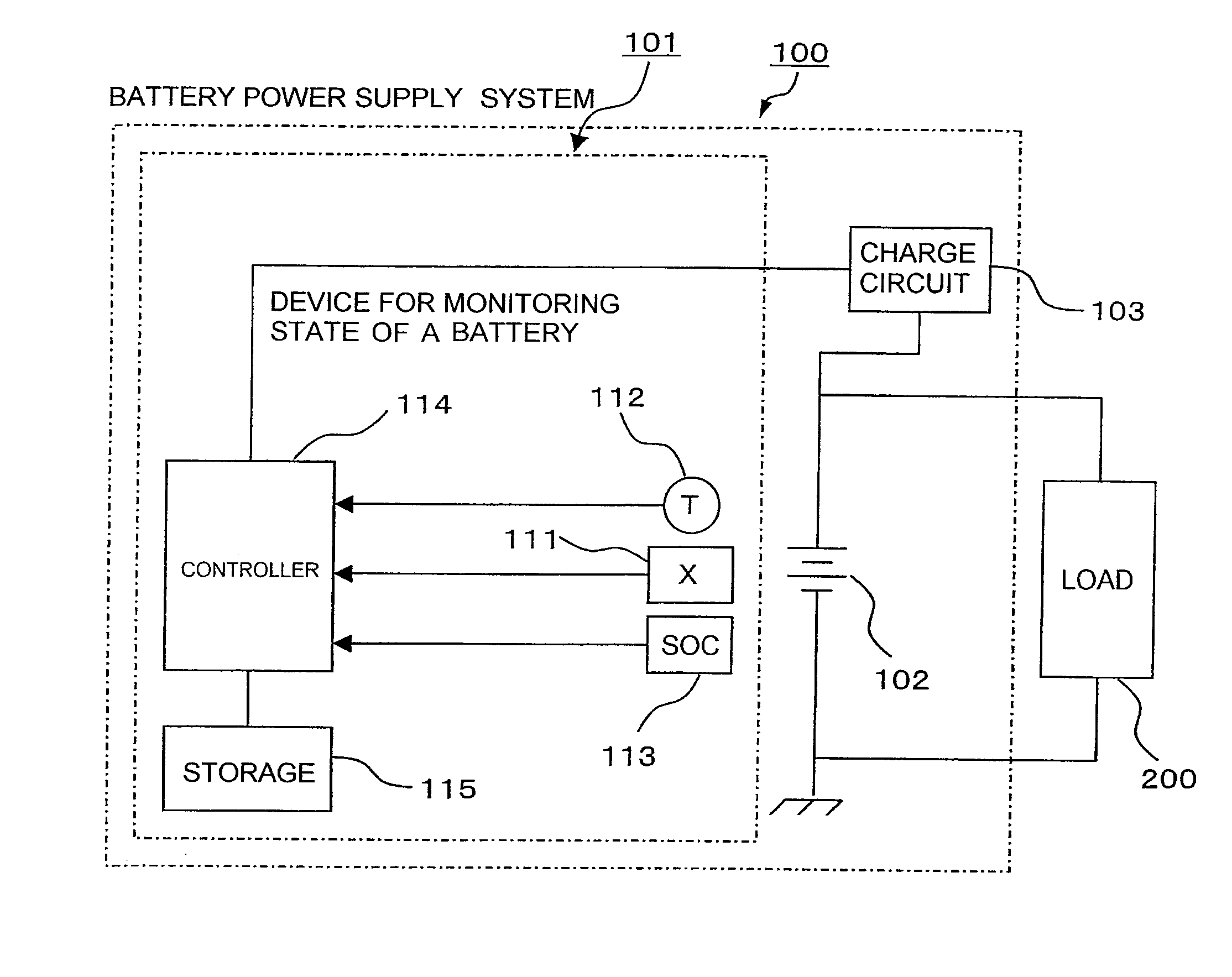
[0083]A method for determining state of a battery, a device for monitoring state of a battery, and battery power supply system in preferable embodiments of the present invention are explained in detail, with reference to the attached drawings.

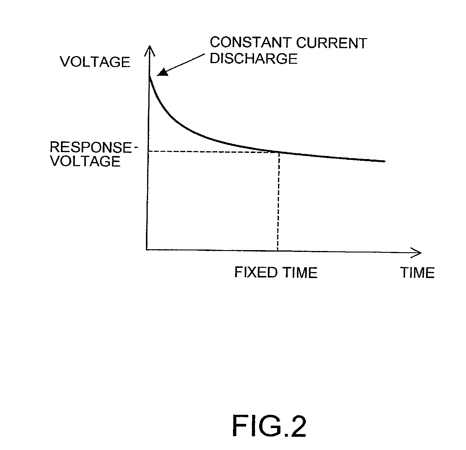
[0084]In a method for determining state of a battery of the present invention, SOF or SOH of a battery is determined based on whether response voltage when a prescribed constant current is discharged from the battery is bigger than a threshold or not.

[0085]Specifically, as shown in FIG. 2, a constant current, for example, 10 A or 100 A is discharged, it is determined whether SOF or SOH of a battery is appropriate or not, based on whether the response voltage value is bigger than a threshold value or not, at a time when a fixed time is passed after the start of the discharge. The magnitude of the discharge current of which the response voltage is to be estimated, or a threshold or the like for determining SOF or SOH of a battery may be determine...


PUM


Abstract

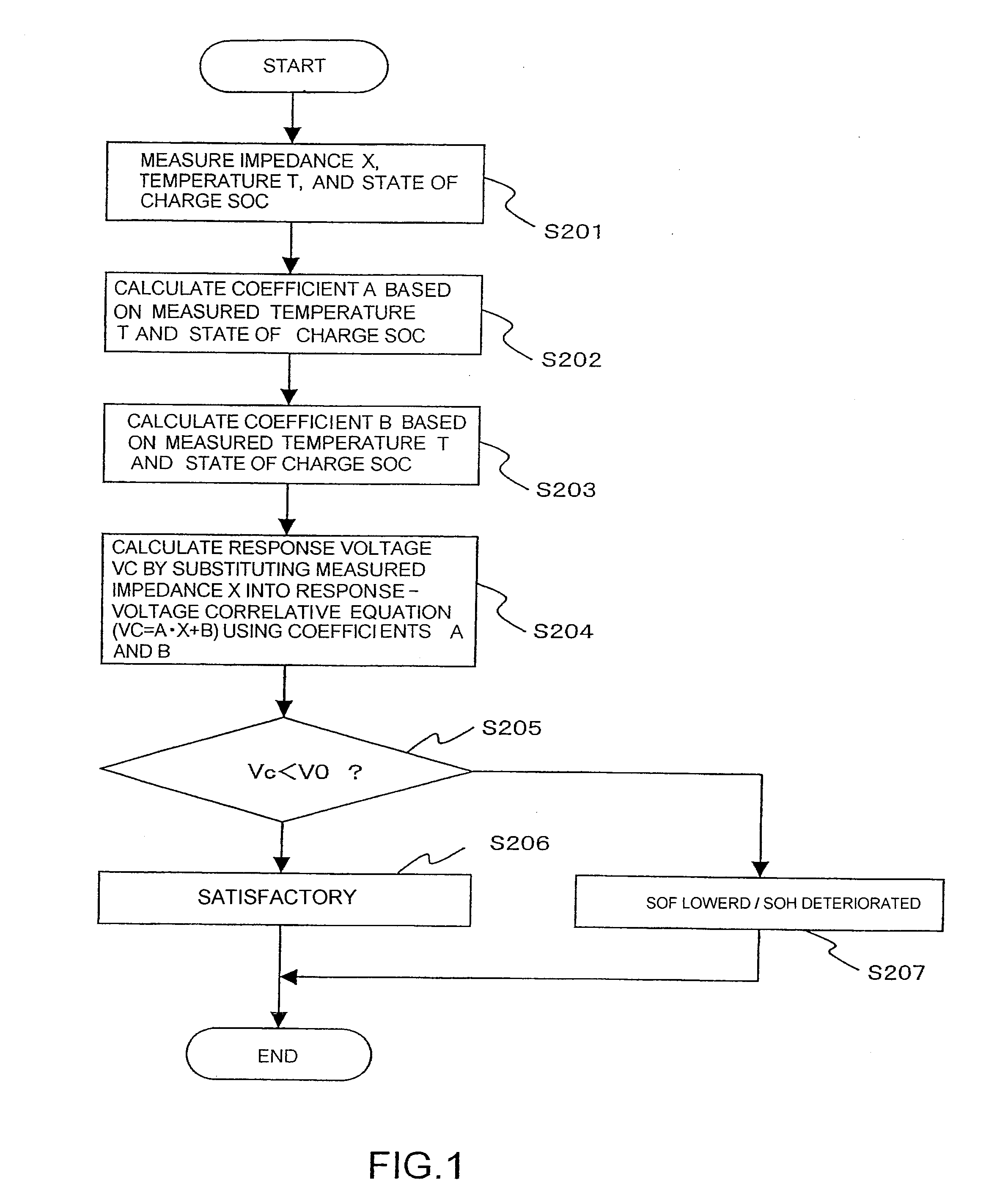
Coefficients A and B are calculated from the measured temperature and the measured state of charge. Next, a response voltage Vc is calculated by substituting the measured internal impedance X into a response-voltage correlation equation. Besides, by comparing the response voltage Vc with a predetermined threshold V0, if Vc is bigger than or equal to V0, the battery is determined as normal. By substituting the measured values of internal impedance, temperature, and SOC into the internal impedance calculation formula, a final internal impedance calculation formula is determined by calculating the value of C by an iterating operation. Next, in the case of determining SOH of a battery, by substituting a standard temperature and a standard SOC into the final internal impedance calculation formula, the internal impedance to determine the SOH is calculated. By comparing the internal impedance with SOH determination threshold, the SOH of the battery is determined.

Description

BACKGROUND OF THE INVENTION[0001]1. Field of the Invention[0002]The present invention relates to a method and a device for determining state of a battery, and a battery power supply system, for determining SOF or SOH of a battery.[0003]2. Related Arts[0004]The technology for determining state of function (SOF) (i.e., discharge capability) or state of health (SOH) (i.e., deterioration level) of a battery by monitoring a battery is, especially in the field of vehicles or the like, an extremely important technology in order to achieve safe and comfortable driving. A method for determining SOF or SOH of a battery has been proposed until now. For example, a method disclosed in Japanese Patent Application Publication No. 2005-037380 has been known.[0005]As for the method disclosed in Japanese Patent Application Publication No. 2005-037380, SOF or SOH of a battery is determined on the basis of the internal impedance or internal resistance of a battery. That is, when the response voltage ca...

Claims


Application Information

Patent Timeline
IPC IPC(8): G01R31/36G06F19/00H01M10/48
CPCG01R31/3662G01R31/3679G01R31/3675G01R31/392G01R31/389G01R31/374
Inventor IWANE, NORIYASUCHIKAZAWA, KEIKOMORII, KEISUKE
Owner FURUKAWA ELECTRIC CO LTD
Learn More