
Gas reservoir evaluation and assessment tool method and apparatus and program storage device

a gas reservoir and tool technology, applied in the field of computer modeling of gas reservoirs, can solve the problems of large amount of reliable data, time-consuming and laborious, and the complete study, including the history matching step, may take months to carry ou

Active Publication Date: 2008-05-22
SCHLUMBERGER TECH CORP
View PDF70 Cites 15 Cited by
  • Summary
  • Abstract
  • Description
  • Claims
  • Application Information

AI Technical Summary

Benefits of technology

The present invention relates to a method and system for generating a computer model of a reservoir based on input data characterizing the reservoir. The method involves calculating the values in one dimension associated with a single layer in the reservoir, each value existing at a single point in space and time in the reservoir. These values are then used to calculate the values in the one dimension associated with multiple layers in the reservoir, each value in each layer existing at a single point in space and time in the reservoir. The values in three dimensions associated with the multiple layers in the reservoir are then calculated, and these values are used to calculate the values as a function of time. The computer model is then verified and used to generate a prediction of the values in the reservoir. The technical effect of this invention is the ability to accurately predict the values in a reservoir based on the input data characterizing the reservoir.

Problems solved by technology

However, in order to make full use of such a tool, a large amount of reliable data is required.
Also, a full study, including the history matching step, may take months to carry out.

Method used


Image

  • Gas reservoir evaluation and assessment tool method and apparatus and program storage device
  • Gas reservoir evaluation and assessment tool method and apparatus and program storage device
  • Gas reservoir evaluation and assessment tool method and apparatus and program storage device

Examples


Embodiment Construction

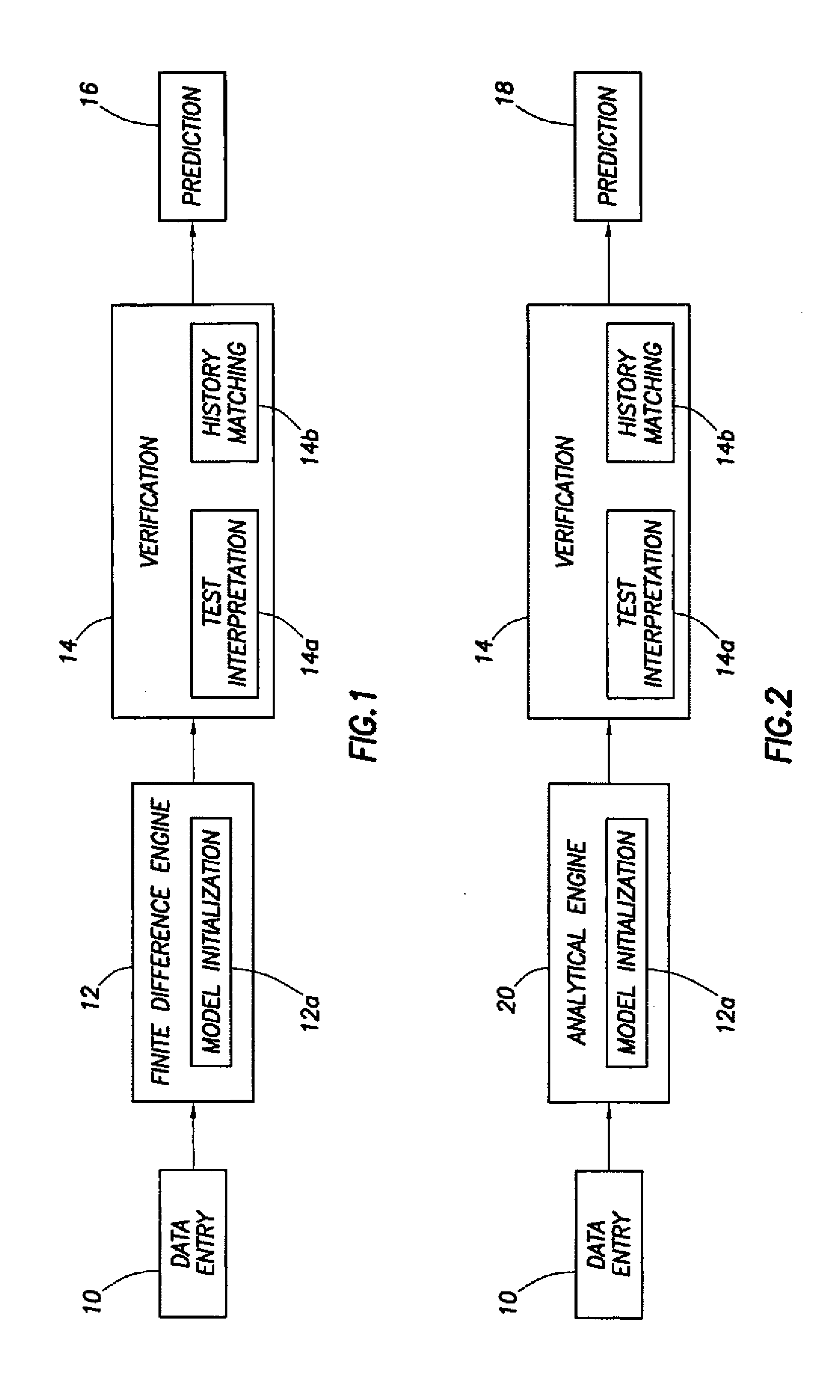
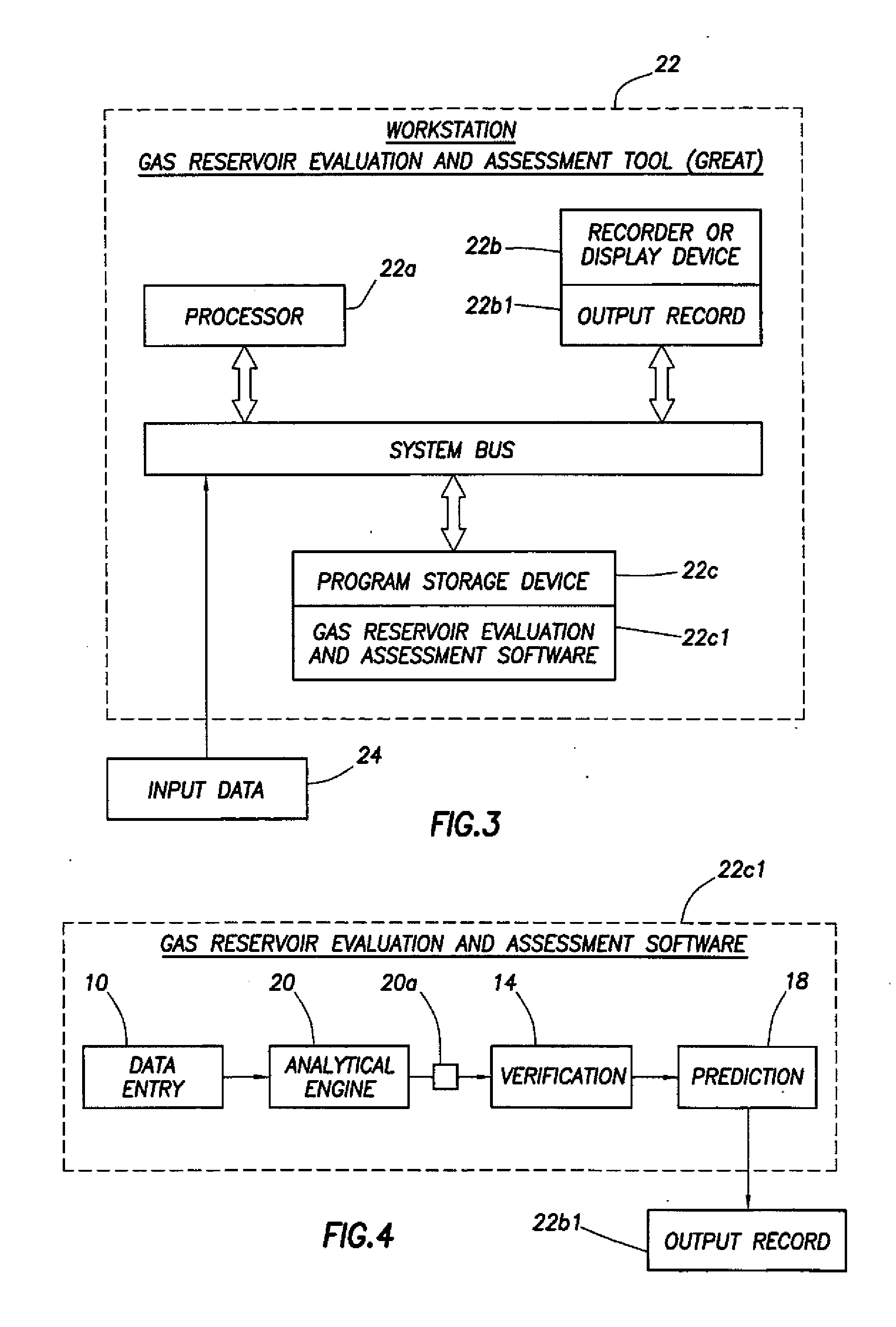
[0017] Prediction of the pressure-production behavior of a hydrocarbon reservoir is essential for its effective management. Project planning and screening functions depend on time availability of such information. There is a need for a fast solution that involves history matching and subsequent prediction. A Gas Reservoir Evaluation and Assessment Tool (GREAT) disclosed in this specification is based around a newly formulated set of equations applicable to multiple wells in a single-phase system. The GREAT tool provides a complete workflow for gas reservoir evaluation comprised of data entry and manipulation, model initialization, test interpretation, history matching and prediction. The GREAT tool includes the Analytical Engine 20 which further includes a newly derived solution of diffusivity equations for multiple wells, horizontal or vertical, in a single phase layered system under a variety of boundary conditions. The solution of these equations model both transient and steady s...


PUM


Abstract

A Gas Reservoir Evaluation and Assessment Tool utilizes an Analytical Engine to produce predictions of pressure values and other production data at any point in space and at any point in time in a reservoir. A computer system, such as a workstation, stores a Gas Reservoir Evaluation and Assessment software which includes the Analytical Engine and responds to input data (which includes a reservoir description and fluid properties) by generating an output record which represents a prediction of the pressure values and other data at ‘any point in space’ and at ‘any point in time’ in a reservoir. The Analytical Engine will first calculate a pressure value in 1D for a single layer of a reservoir at a single point in space and time; it will then calculate a pressure value in 1D for multiple layers in the reservoir at the single point in space and time; it will then calculate a pressure value in 2D for the multiple layers at the single point in space and time; it will then calculate a pressure value in 3D for the multiple layers at the single point in space and time; and it will then calculate a pressure values in 3D for multiple layers not only at a single point in space but also at any future point in time.

Description

CROSS REFERENCED TO RELATED APPLICATIONS [0001] This application is a continuation of prior application Ser. No. 10 / 723,479, filed Nov. 25, 2003, corresponding to attorney docket number 94.0073.BACKGROUND OF THE INVENTION [0002] The subject matter of the present invention relates to computer modeling of a gas reservoir, and, more particularly, to a method and apparatus and program storage device adapted for generating a computer model which will predict the pressure and the production behavior of a gas reservoir. [0003] Reservoir simulation is an essential tool for the management of oil and gas reservoirs. Prediction of the pressure in and the production of a gas reservoir under various operating conditions allows, among other benefits, proper investment decisions to be made. In order to make such a prediction, one must construct a reservoir model. The reservoir model is essentially a mathematical model that is implemented through a computer program. History matching observed behavi...

Claims


Application Information

Patent Timeline
Patent Type & Authority Applications(United States)
IPC IPC(8): G06F7/57
CPCG01V11/00
Inventor THAMBYNAYAGAM, RAJSPATH, JEFFREYBANERJEE, RAJGILCHRIST, JOHNMILLER, TOMMY
Owner SCHLUMBERGER TECH CORP
Learn More