Percutaneous gastrointestinal anchoring kit

a percutaneous gastrointestinal and kit technology, applied in the field of surgical kits, can solve the problems of irritating the stomach lining, minor erosion of the device, and the inability to easily remove the initial placement devi

Active Publication Date: 2008-05-29
AVENT INC
View PDF54 Cites 42 Cited by
  • Summary
  • Abstract
  • Description
  • Claims
  • Application Information

AI Technical Summary

Benefits of technology

[0012]In another embodiment, an apparatus for insertion into a body orifice for anchoring a first body tissue layer to a second body tissue layer would have a hollow, collapsible, microthin polymeric shaft affixed to a noncollapsible tip at a distal end of the polymeric shaft. A preformed balloonable distention formed in a discrete region of the shaft proximal to the noncollapsible tip would be adapted to anchor against one of the body tissue layers within the body orifice. A rod may be attached at one en...

Problems solved by technology

Although these devices perform the function that they are designed for, a number of problems do exist with them.
Consequently, in many cases these initial placement devices are often not readily removable without additional invasive surgical procedures.
This is further complicated by the fact that during the six to eight weeks it takes for the fistula's stoma tract to be established, the anchoring mechanism i.e., the small metal T-shaped fastener may embed itself into the gastric or intes...

Method used


Image

  • Percutaneous gastrointestinal anchoring kit
  • Percutaneous gastrointestinal anchoring kit
  • Percutaneous gastrointestinal anchoring kit

Examples


second embodiment

[0048]In a second embodiment depicted in FIG. 8, a multicomponent design may be used to secure the anchor 20 in place. One example may utilize a base plate 53 for seating against the patient's body, and a lid or cap 54 secured to the cap to cover the base plate 53 as well as that portion of the anchor 20 protruding from the body. The base plate 53 may be configured similarly to the FIG. 7 retainer in that it would possess a slot 51 or central opening which would enable the base plate to secure the shaft 23. The shaft 23 may be pulled under tension and wedged or otherwise secured into the base plate 53, for example, by engaging the shaft 23 with a fixture 55 such as by passing the anchor 20 through the fixture 55 and wrapping the shaft 23 around the fixture to secure the shaft 23 in a manner reminiscent of tying a line to a cleat. This configuration may also be covered with a bandage as described above, or the cap 54 may be secured over the base plate 53. The base plate 53 and cap 54...

third embodiment

[0049]the retainer 50, may be similar to that depicted in U.S. patent application Ser. No. 11 / 139,927 filed on May 27, 2005 entitled “Clamp for Flexible Tube” which is copending and commonly assigned, the disclosure of which is herein incorporated by reference in its entirety.

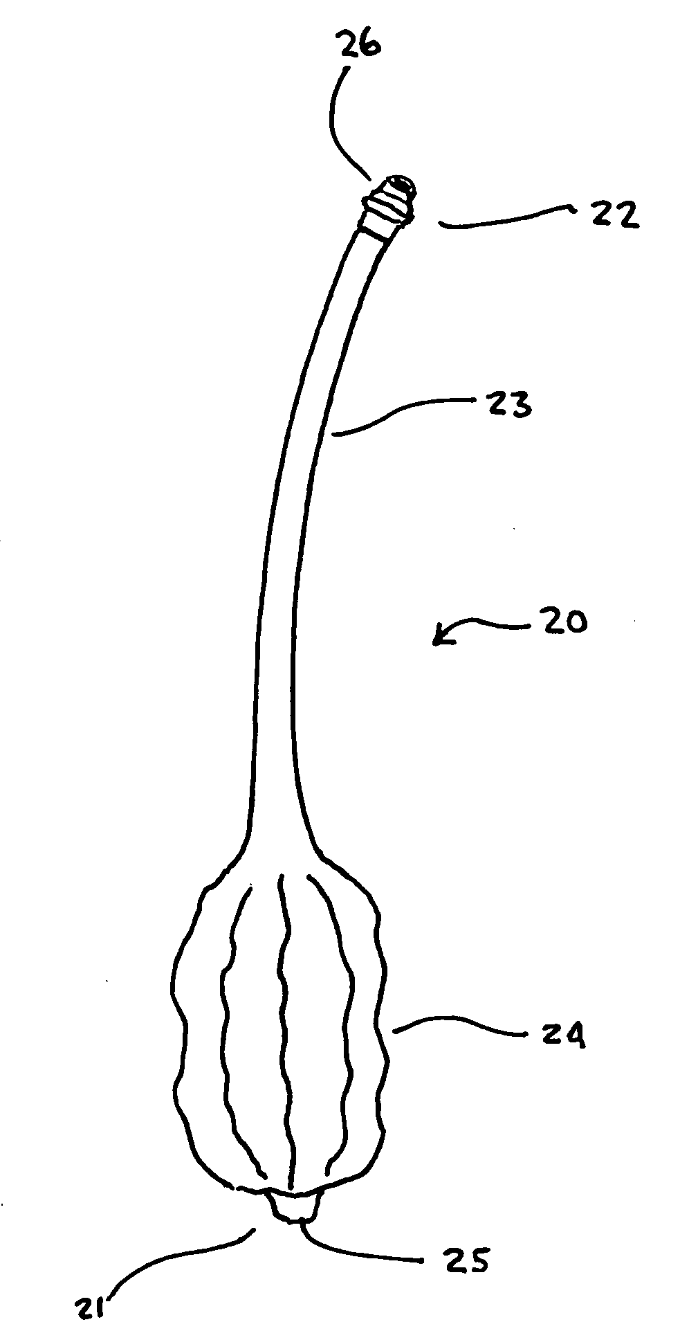
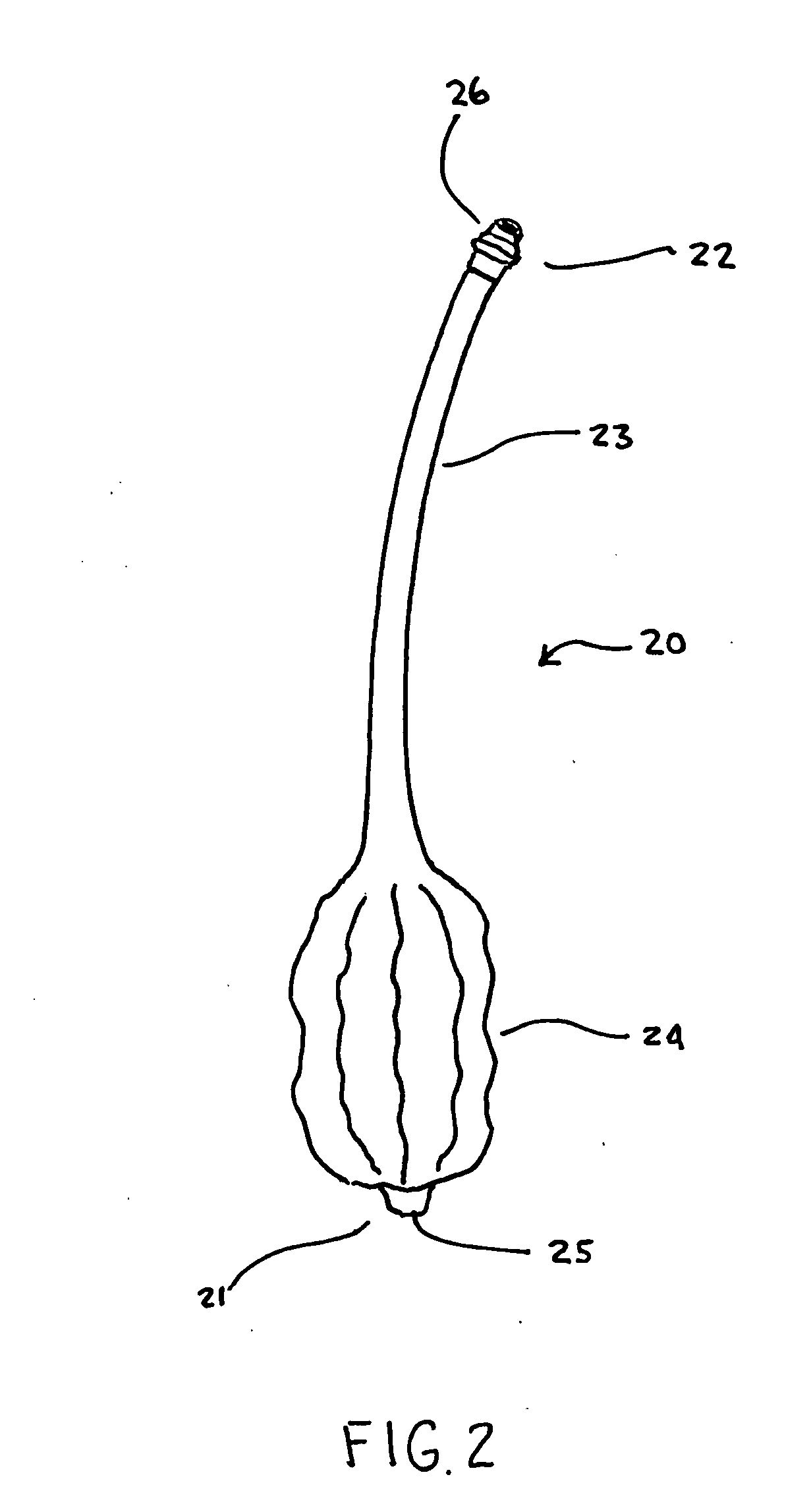
[0050]FIG. 9 depicts the anchor 20 in place within a body 100. As may be seen the inflator 60 is connected to the anchor 20 at the connector 26. Due to the small size of the anchor 20, the inflator 60 may simply be a syringe capable of injecting into as well as removing a fluid from the anchor 20. Although in many instances, the fluid is air, it should be understood that the ballooned region 24 may be inflated and deflated upon application or removal of other fluids, both gaseous and liquid, including but not limited to water and saline. In the FIG. 9 embodiment, it may be seen how the anchor 20 is used to secure the gastric wall 101 to the abdominal wall 102 by entering the patient's body 100 into the stomach ...


PUM

PropertyMeasurementUnit
Forceaaaaaaaaaa
Diameteraaaaaaaaaa
Permeabilityaaaaaaaaaa

Abstract

The invention describes a percutaneous gastrointestinal anchoring kit having an anchor, an introducer, a guide, an inflator, and a retainer. The anchor contains a ballooned region and a shaft portion. The retainer secures the anchor within the stomach when the ballooned region is inflated by seating against an exterior surface of the patient body and placing a tractive force on the ballooned region so as to pull the gastric lumen to an interior abdominal wall of the patient body. The introducer is used to insert the anchor initially within the stomach. The guide positions the ballooned region of the anchor within the stomach by enabling manipulation from an exterior surface of the patient body. The inflator is used to selectively inflate or deflate the ballooned region as needed.

Description

BACKGROUND OF THE INVENTION[0001]The present invention relates to pre-packaged surgical kits in general, and more particularly to surgical kits for percutaneous gastrointestinal anchoring procedures or a gastropexy kit.[0002]Various medical procedures are simplified by providing the physician with a kit that contains the majority, if not all, of the necessary medical articles that the physician will need to complete a particular procedure. Kits may include articles such as, for example, drapes, syringes, scalpels, needles, clamps, gauze, sponges, drugs, sutures, and devices. Such kits are commonly provided for procedures such as, for example, percutaneous endoscopic gastrostomy (“PEG”) and laparoscopic jejunostomy. These kits reduce the time spent by hospital personnel gathering the appropriate articles that are required for a particular procedure and ensure that the surgeon has each article at hand at the appropriate point in the procedure.[0003]A PEG procedure is utilized to place...

Claims


Application Information

Patent Timeline
IPC IPC(8): B65D69/00A61M25/04A61B19/02B65D1/34A61F13/00A61F2/958
CPCA61B17/0218A61B17/0401A61B19/026A61B2017/00557A61B2017/0404A61M2025/0286A61B2019/307A61M25/02A61M25/10A61M2025/024A61M2025/028A61B2017/0409A61B50/30A61B2090/037
Inventor GOBEL, FRED
Owner AVENT INC
Why Eureka
Try Eureka