Fluid clarification system, method, and apparatus

a technology of fluid clarification and flue, applied in the field of fluid clarification system, method and apparatus, can solve the problems of inability to selectively remove thickened solids from the settling tank, difficulty in emptying and cleaning prior art tank systems, and clogging or jamming of solids, so as to reduce the loading rate of the weir wall

Inactive Publication Date: 2008-05-29
GODLIEN SCOTT BLAIR
View PDF32 Cites 20 Cited by
  • Summary
  • Abstract
  • Description
  • Claims
  • Application Information

AI Technical Summary

Benefits of technology

[0029]In a suitable embodiment, the weir wall between each successive settling compartment is reduced in height from the previous weir wall so as to direct overflow fluid through the settling compartments in succession. One or more of the weir walls may be notched, angled, or have one or more horizontally protruding weir plates to reduce the loading rate of the weir wall.

Problems solved by technology

Such solids removal systems involve mechanical parts which require maintenance and may also become clogged or jammed with solids during use.
Moreover, the prior art tank systems are difficult to empty and clean following completion of drilling.
This generally requires a series of centrifuges to dewater the solids stream, as selective removal of thickened solids from the settling tank is not possible.
Such selective solids removal is not possible using the solids conveying means of current horizontal settling tank systems.

Method used


Image

  • Fluid clarification system, method, and apparatus
  • Fluid clarification system, method, and apparatus
  • Fluid clarification system, method, and apparatus

Examples


example

[0075]The following example describes the general construction and testing of a system constructed in accordance with an embodiment of the invention.

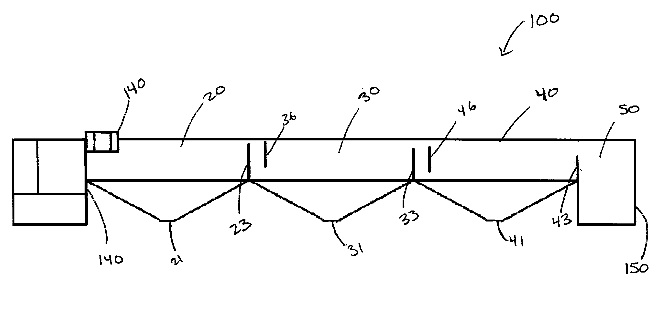
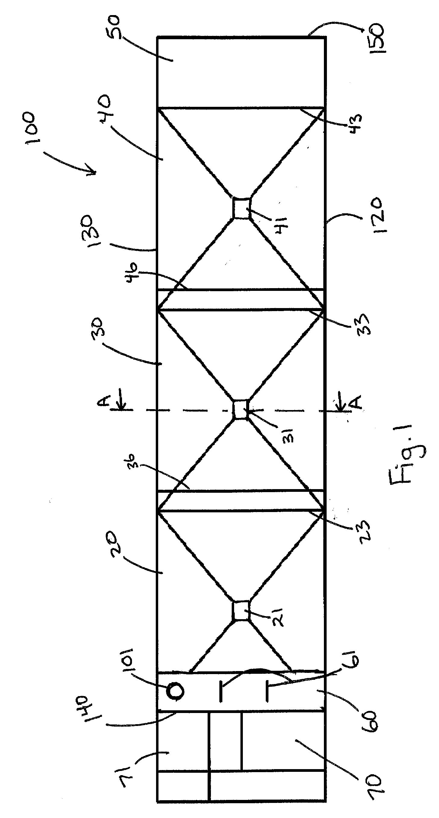
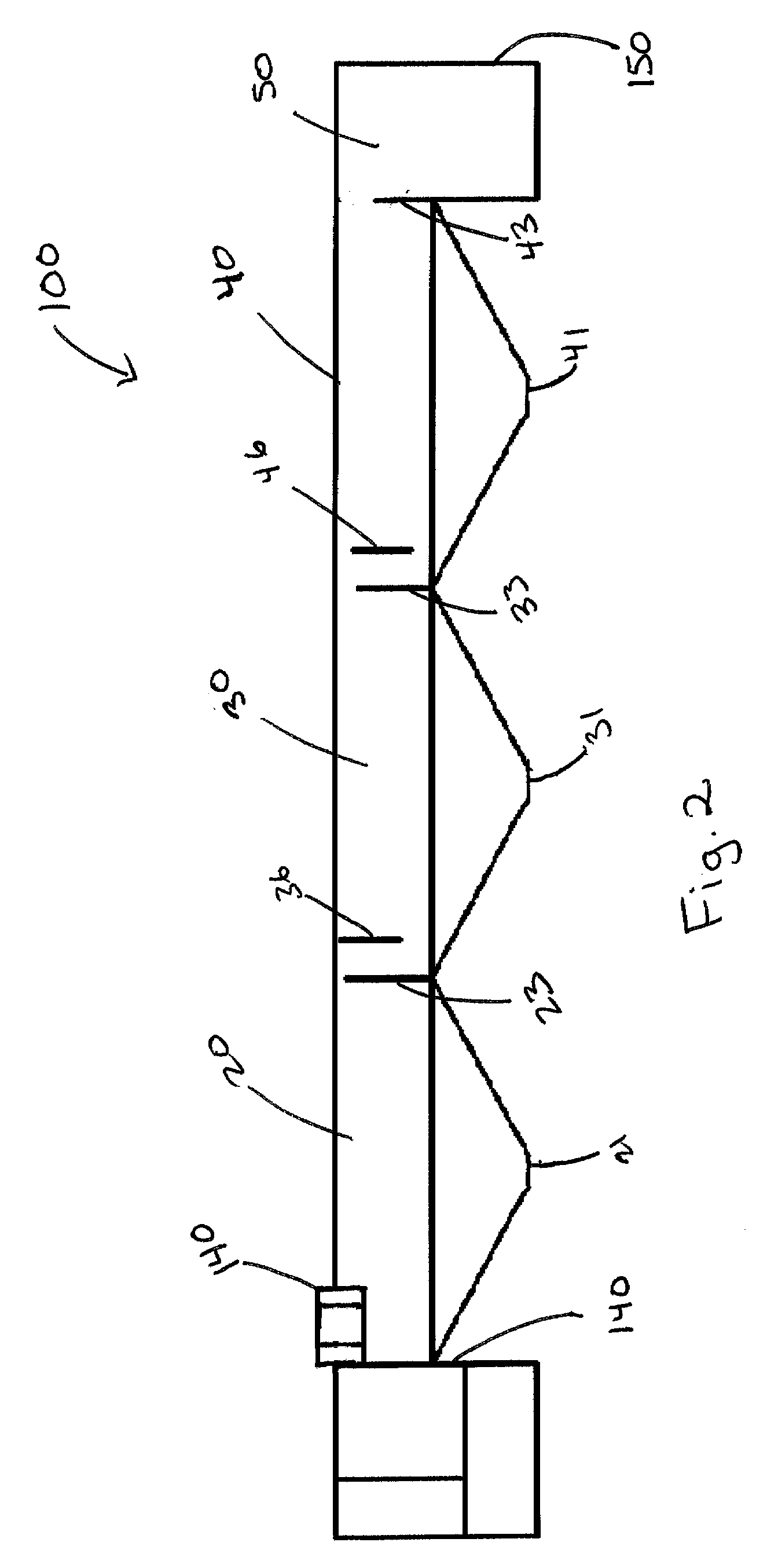
[0076]A skid-mounted horizontal settling tank (11.55 m long×2.74 m wide×1.70 m high) was divided by three weir walls into three settling compartments (3.04 m×2.74 m) and a clear fluid compartment (1.06 m×2.74 m), as shown in FIG. 1. A polymer hydrating system (1.37 m×2.74 m) was placed adjacent the first settling compartment, and a flocculant reaction trough (0.60 m×2.74 m) was placed within the first settling compartment as shown. The base of each settling compartment was created by joining four triangular panels into an inverted pyramid, with a solids outlet cut from the lowermost portion of one of the triangular panels. Once assembled, the base was 0.88 m high, and was attached to the walls at a depth of 0.82 m from the top of the tank. The triangular panels extending from the tank side walls were inclined towards the solids outlet a...


PUM

PropertyMeasurementUnit
angleaaaaaaaaaa
angleaaaaaaaaaa
angleaaaaaaaaaa

Abstract

A fluid clarification system and method is described in which fluid is passed through one or more settling compartments, each having a solids outlet at the base of the compartment. The base of each compartment includes inclined surfaces for guiding settled solids to the outlet. Also described is a polymer reaction trough including baffles to promote gentle mixing of inflow fluid with flocculant. The system is designed to reduce costs of transportation, flocculent, and solids handling. The system is preferably arranged to facilitate transport on a skid or trailer, while maximizing fluid handling capabilities and minimizing costs.

Description

FIELD OF THE INVENTION[0001]The present invention relates generally to the clarification of fluids. More particularly, the present invention relates to a system, method, and apparatus for separating suspended solids from a fluid stream to produce a clarified fluid stream and a solids output stream.BACKGROUND OF THE INVENTION[0002]Downhole drilling operations are generally performed at remote locations, and it is therefore desirable to reuse or recycle as many resources as possible on-site to avoid excessive environmental damage and reduce unnecessary transportation costs. In addition, any other means to reduce equipment, material, and transportation costs is desirable.[0003]During clearwater drilling, water is pumped downhole through the drill string to the drill bit, and is returned to the surface as a slurry, carrying cuttings and suspended solids. The slurry is then clarified and the resulting clear water is recycled for use in further drilling. At various stages of drilling, dif...

Claims


Application Information

Patent Timeline
Patent Type & Authority Applications(United States)
IPC IPC(8): B01D21/24C02F1/52
CPCB01D21/0003B01D21/0042B01D21/0093B01D21/08B01D21/2427B01D21/245B01D21/262B01D21/305B01D21/0039B01D21/26B01D21/003
Inventor GODLIEN, SCOTT BLAIR
Owner GODLIEN SCOTT BLAIR
Why Eureka
Try Eureka