Surgical instrument support

a surgical instrument and support technology, applied in the direction of surgical instrument support, machine support, application, etc., can solve the problem that the support nevertheless has certain limitations

Inactive Publication Date: 2008-05-29
FETZER PETER E
View PDF13 Cites 24 Cited by
  • Summary
  • Abstract
  • Description
  • Claims
  • Application Information

AI Technical Summary

Benefits of technology

[0008]According to another embodiment, the arm segments have a first end, a second end, and a hollow aperture portion extending therebetween. In one embodiment the first end of the mating arm segments has a male mating geometry, and the second end of the mating arm segments has a female mating geometry. The female mating geometry of the mating arm segments is adapted to mate with the male mating geometry of an adjacent mating arm segment. According to another embodiment, the mating surfaces have different surface hardness and surface roughness to assist in preventing slipping between the components in the rigid configuration.
[0013]According to another embodiment, the surgical instrument support comprises an end arm member adjacent a last of the mating arm segments, the end arm member comprising a retainer having a bore to removably secure the line therein, and a collar having central bore to seat the retainer therein and a second end configured to mate with the first end of the last of the mating arm segments. Additionally, the end arm member comprises a connector member removably secured to the collar of the end arm member. The connector has a securing member to removably connect a surgical instrument to the surgical instrument support. In a preferred embodiment the connector member can be removed from the end arm member without the line releasing the arm segments and without the line having to be moved to the non-actuated or loose condition.
[0015]According to another embodiment, the collar has a stepped bore to assist in removably seating the retaining in the collar.

Problems solved by technology

While such surgical instrument supports according to the prior art provide a number of advantageous features, they nevertheless have certain limitations.

Method used


Image

  • Surgical instrument support
  • Surgical instrument support
  • Surgical instrument support

Examples


Embodiment Construction

[0025]While this invention is susceptible of embodiments in many different forms, there is shown in the drawings and will herein be described in detail preferred embodiments of the invention with the understanding that the present disclosure is to be considered as an exemplification of the principles of the invention and is not intended to limit the broad aspect of the invention to the embodiments illustrated.

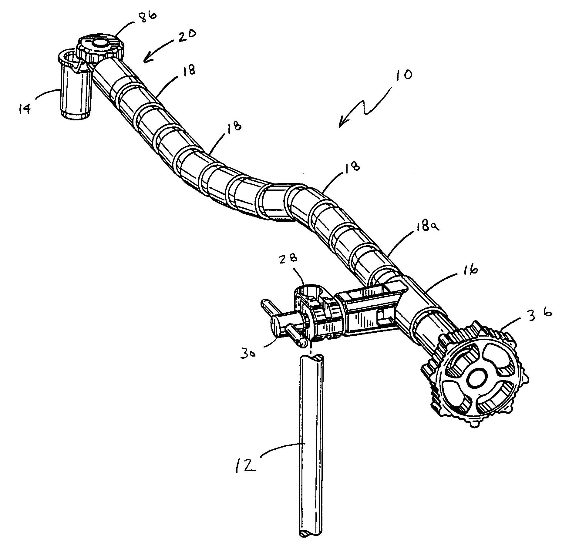
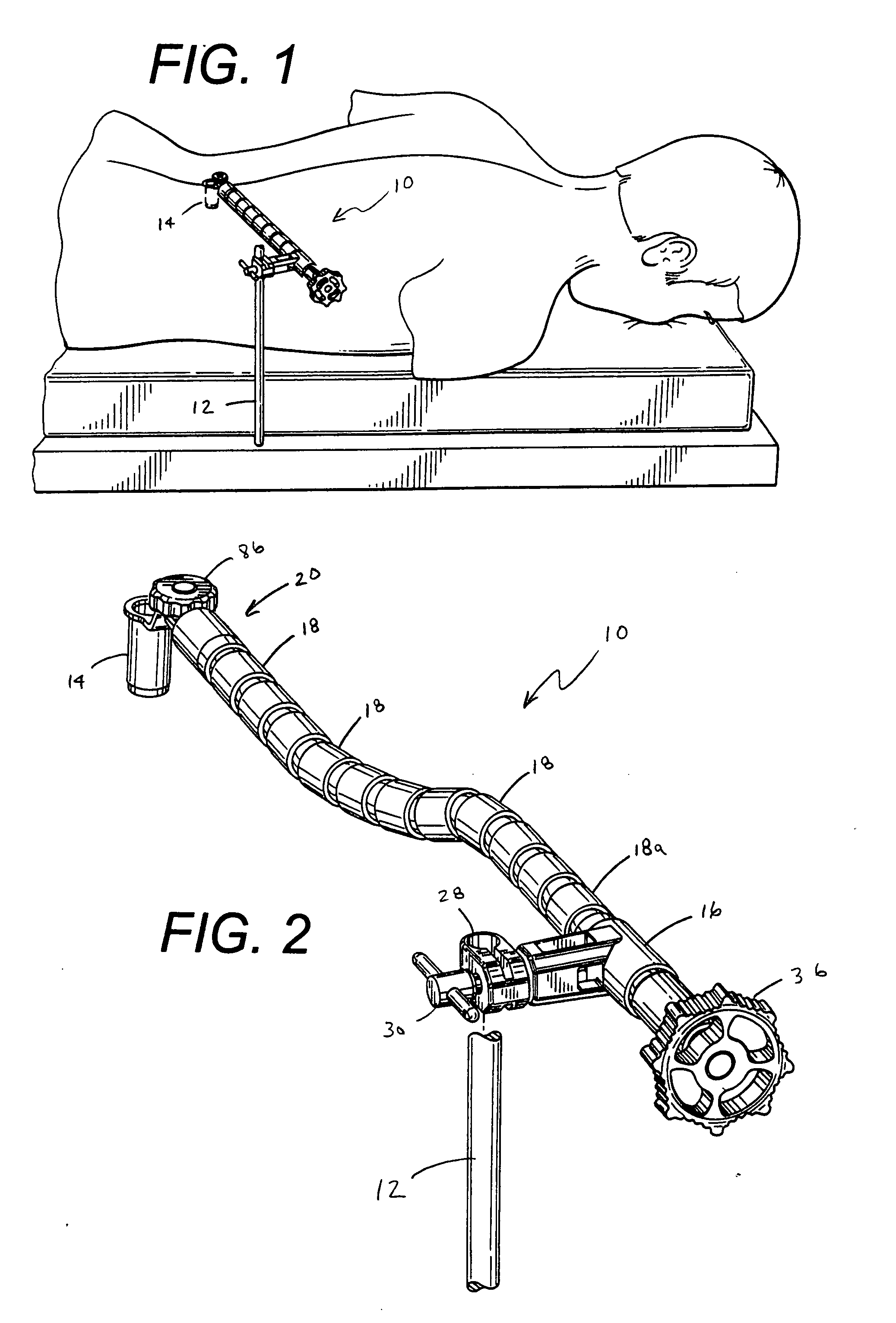
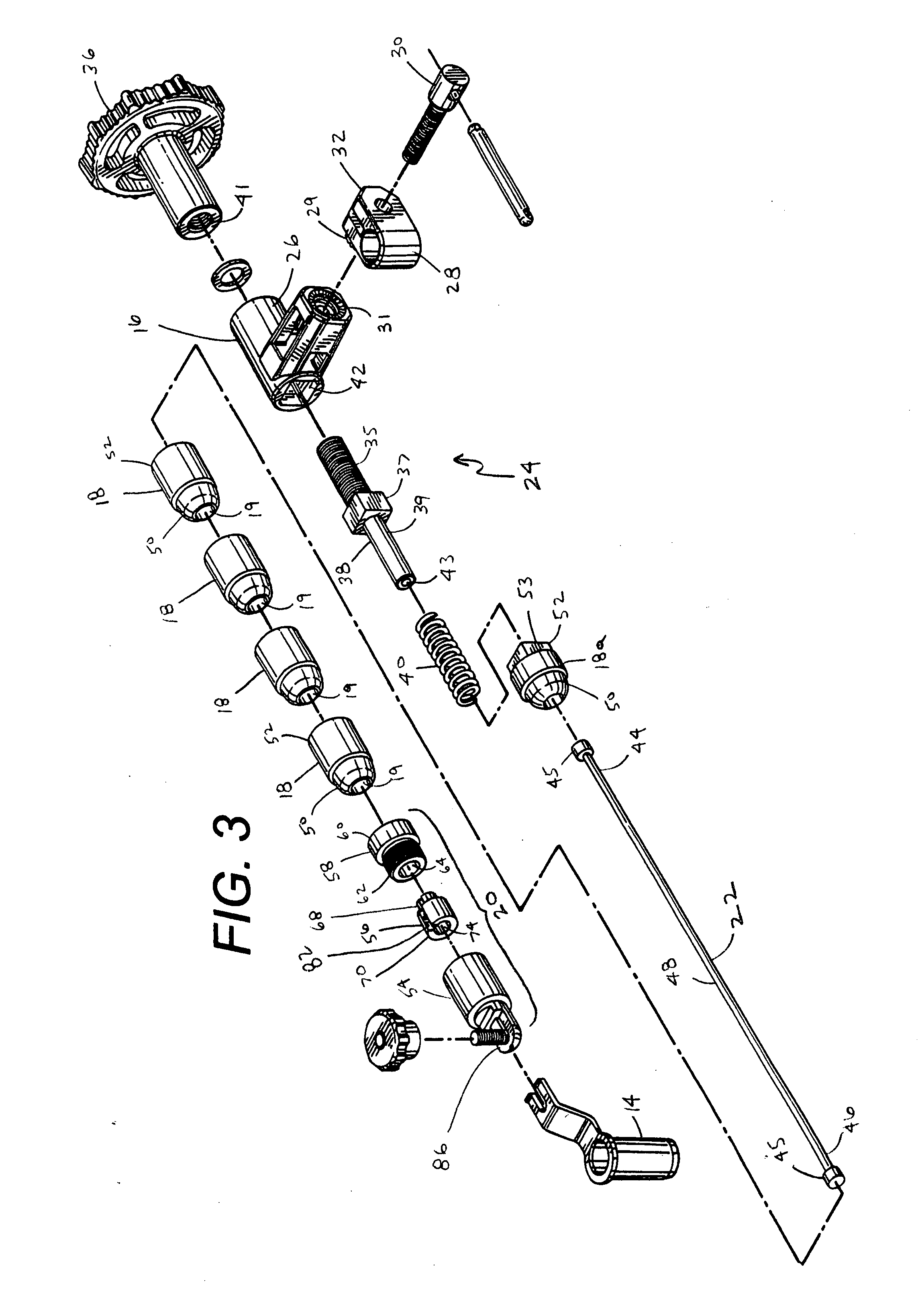
[0026]Referring now to the Figures, and specifically to FIGS. 1-3, there is shown a surgical instrument support 10 in the actuated or use position (FIG. 1), and the normal or non-use position (FIGS. 2 and 3). As shown in FIG. 1, the surgical instrument support 10 is a component that is supported on one end to a fixed member 12, such as a post extending from a surgical table 12, and is cantilevered outward from the fixed member 12 to fix a surgical instrument 14, connected to the distal end of the surgical instrument support 10, in a position desired by the surgeon.

[0027]In one ...


PUM


Abstract

The present invention generally provides a surgical instrument support for securing a surgical instrument in a fixed position in a surgical environment having a magnetic field. The surgical instrument support has a mounting clamp, a tightening mechanism, a plurality of mating arm segments, an end member with a connector to secure the surgical instrument thereto, and a wire extending from the tightening mechanism to the end member. The wire can be tightened to secure the mating arm segments in a desired position for the surgeon. In one embodiment all of the components of the surgical instrument support are made of a non-magnetic material, preferably titanium or a titanium alloy. In another embodiment the connector of the end member can be removed when the surgical instrument support is in both the rigid or actuated configuration and the untightened or non-actuated configuration.

Description

CROSS-REFERENCE TO RELATED APPLICATIONS[0001]Not Applicable.FEDERALLY SPONSORED RESEARCH OR DEVELOPMENT[0002]Not Applicable.TECHNICAL FIELD[0003]The present invention relates to a support for a surgical instrument, and more specifically to titanium tightening mechanisms for supporting surgical instruments within a magnetic field.BACKGROUND OF THE INVENTION[0004]Surgical instruments and supports for surgical instruments are well known in the art. While such surgical instrument supports according to the prior art provide a number of advantageous features, they nevertheless have certain limitations. The present invention seeks to overcome certain of these limitations and other drawbacks of the prior art, and to provide new features not heretofore available. A full discussion of the features and advantages of the present invention is deferred to the following detailed description, which proceeds with reference to the accompanying drawings.SUMMARY OF THE INVENTION[0005]The present invent...

Claims


Application Information

Patent Timeline
Patent Type & Authority Applications(United States)
IPC IPC(8): A61B19/00
CPCA61B2017/00911A61B90/50A61B2090/571
Inventor FETZER, PETER E.
Owner FETZER PETER E
Why Eureka
Try Eureka