
Knee airbag device

Inactive Publication Date: 2008-05-29
TOYOTA JIDOSHA KK
View PDF5 Cites 16 Cited by
  • Summary
  • Abstract
  • Description
  • Claims
  • Application Information

AI Technical Summary

Benefits of technology

[0007]The invention provides a knee airbag device that reduces strength of a force by which an airbag door presses the knees of an occupant when a knee airbag is inflated and deployed.
[0009]According to the above-described aspect, when a collision occurs, the gas generation device is operated to generate gas. The gas flows into the knee airbag that is stored in the folded state inside the column cover that covers the rear end portion of the steering column. Thus, the knee airbag is inflated. Accordingly, the airbag inflation pressure is applied to the airbag door provided in the lower portion of the column cover, and thus, the airbag door is opened. As a result, the knee airbag is inflated and deployed toward the knees of the occupant, and protects the knees of the occupant.
[0016]In the above-described aspect, the airbag door may be made of cloth, i.e., a material that is different from a material of which the column cover is made. Therefore, fixing means for fixing the airbag door to the column cover is generally required, because different materials are joined together. However, according to the aspect of the invention, because the base end portion of the airbag door is embedded in the peripheral portion around the opening by insert molding, the resin moves to, and firmly attaches to the base end portion of the airbag door, when the column cover is formed using resin. Accordingly, it is possible to ensure the strength for supporting the airbag door, without providing, for example, special fixing means for fixing the airbag door.

Problems solved by technology

However, in the above-described knee airbag device, because the column cover is made of a relatively rigid resin material, the airbag door may strongly press the knees of the occupant when the knee airbag is inflated and deployed.

Method used


Image

  • Knee airbag device
  • Knee airbag device
  • Knee airbag device

Examples


Embodiment Construction

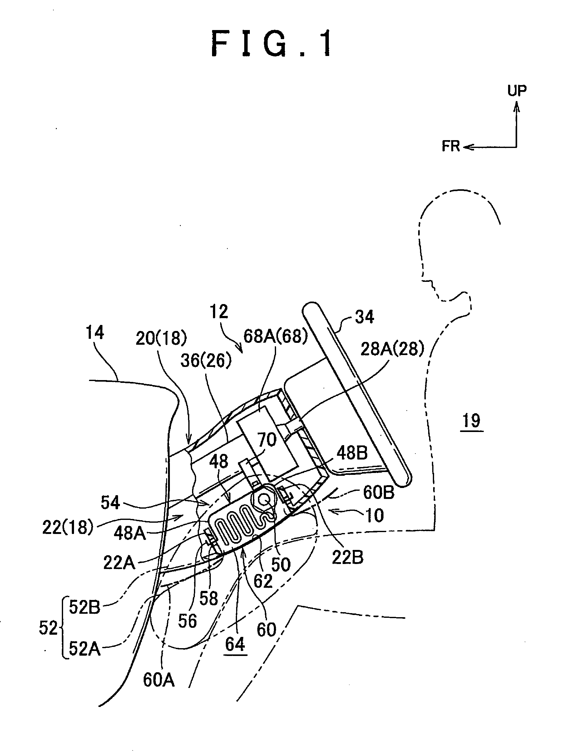
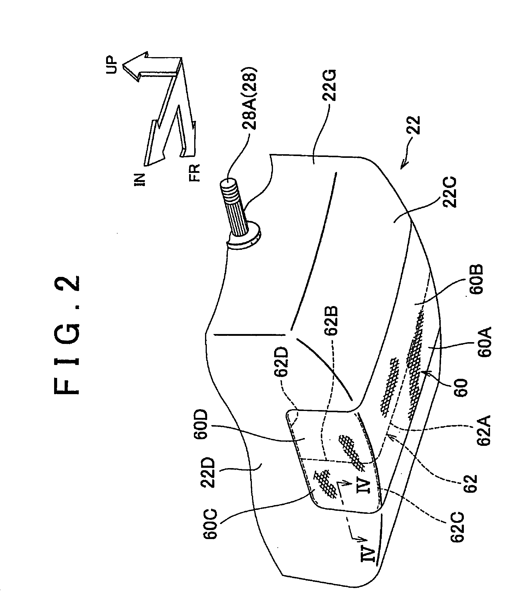
[0022]Hereinafter a knee airbag device for a vehicle according to an embodiment of the invention will be described with reference to FIG. 1 to FIG. 4. In FIG. 1 to FIG. 4, the arrow FR indicates the front of a vehicle. The arrow UP indicates the top of the vehicle. The arrow IN indicates the inside of the vehicle in a vehicle-width direction.

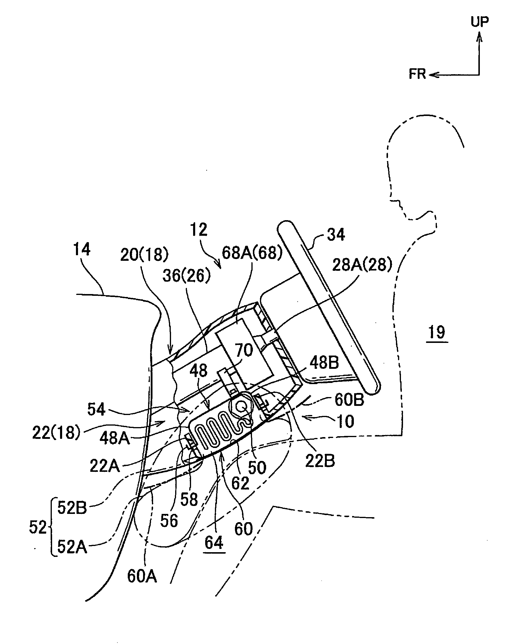
[0023]FIG. 1 is a longitudinal cross sectional view showing the entire configuration of a knee airbag device 10 according to the embodiment FIG. 2 is an enlarged perspective view showing the main portion of the knee airbag device 10.

[0024]As shown in FIG. 1 and FIG. 2, an opening portion is formed in a portion of an instrument panel 14, which faces a driver seat. A steering column 12 is inserted through the opening portion such that the steering column 12 is inclined downward toward the front of the vehicle. The column cover 18 covers the rear end portion of the steering column 12, which protrudes toward a vehicle cabin 19 from the opening porti...


PUM


Abstract

A knee airbag device includes an airbag module and an airbag door. The airbag module includes a gas generation device that is operated when the knee airbag device is operated, and a knee airbag that is stored in a folded state inside a column cover that covers the rear end portion of a steering column. When the knee airbag receives gas from the gas generation device, the knee airbag is inflated and deployed toward the knee of an occupant. The airbag door, provided in the lower portion of the column cover, is made of a flexible material. When the knee airbag is inflated and deployed, the airbag door is opened toward the knee of the occupant due to an airbag inflation pressure.

Description

INCORPORATION BY REFERENCE[0001]The disclosure of Japanese Patent Application No. 2006317353 filed on Nov. 24, 2006 including the specification, drawings and abstract is incorporated herein by reference in its entirety.BACKGROUND OF THE INVENTION[0002]1. Field of the Invention[0003]The invention relates to a knee airbag device that includes a knee airbag that is inflated and deployed from a column cover for a steering column to restrain the knees of an occupant, when a collision occurs.[0004]2. Description of the Related Art[0005]Various knee airbag devices have been proposed to protect the knee portion of an occupant. For example, Japanese Patent Application Publication No. 2002-37003 (JP-A-2002-37003) describes a knee airbag device in which an airbag module is disposed inside a column cover for a steering column. In the knee airbag device, a tear portion formed in the column cover is torn by an airbag inflation pressure, and thus, an airbag door is opened. A knee airbag is inflate...

Claims


Application Information

Patent Timeline
IPC IPC(8): B60R21/20B60R21/203B60R21/206B60R21/215
CPCB60R21/2032B60R2021/23169B60R21/2165B60R21/206
Inventor FUKAWATASE, OSAMUMORO, TOMOYUKIIMAMURA, KENJISANADA, AKIYOSHI
Owner TOYOTA JIDOSHA KK
Learn More