Fractional digital pll

Active Publication Date: 2008-05-29
ZARLINK SEMICON LTD
View PDF9 Cites 13 Cited by
  • Summary
  • Abstract
  • Description
  • Claims
  • Application Information

AI Technical Summary

Benefits of technology

[0018]Embodiments of the invention perform scaling in the amplitude domain, rather than the time domain as in the prior art. This allows the PLL to have maximum bandwidth relative to the input frequency. Embodiments of the invention are able to input every edge of the input signal into the phase detector, unlike in prior art arrangements where only certain edges are input into the phase detector. This also avoids jitter problems that arise when performing such operations in the time domain.

Problems solved by technology

There are a few common methods to implement this fractional relationship, but those are in reality hampered by rather severe limitations in the final performance.
The disadvantage of this approach is that the edges from input signal are not well applied.
This implies:a) The frequency into the phase detector is lower, and so must the maximum bandwidth of the PLL transfer be lower.b) The reduced bandwidth is more difficult to implement.
However, the cost is now that the output of the VCO or CCO is now running on an N times higher frequency.
The disadvantages are apparent:a) There is a fair chance the VCO frequencies are no longer feasible.
Of course the numbers can easily become even more extreme.b) Dividers that divide from the extremely high VCO frequency to lower frequencies become difficult to design.c) The power will rise due to the higher frequency requirement.
Depending on implementation this may reduce the quality.

Method used


Image

  • Fractional digital pll
  • Fractional digital pll
  • Fractional digital pll

Examples


Embodiment Construction

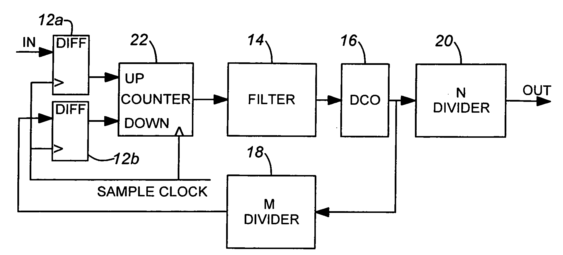
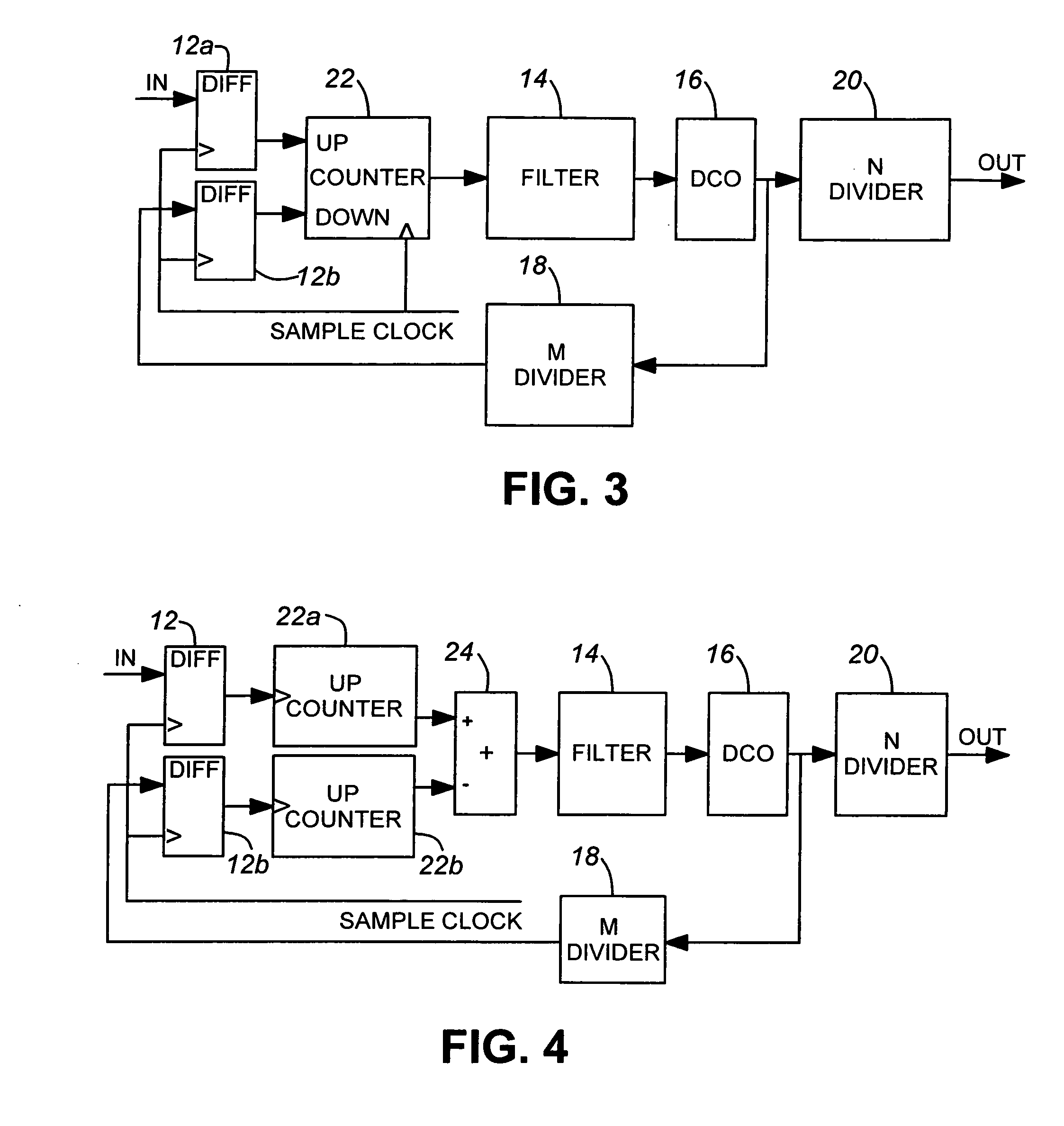
[0034]In order to understand the invention, reference will be made to a subclass of PLL's is a digital PLL as shown in FIG. 3. In such a PLL, the incoming signal is first sampled in unit 12 before being applied to the phase detector 22, which is in the form of an updown counter. In this case, the phase detector is a counter 22 that represents the phase difference up to an extended number of cycles. In the filter this phase difference may be processed, possibly with required decimation, and the PI operation (Proportional-Integral control).

[0035]The size of the counter 22 forming the phase detector determines the maximum range of phase difference for the whole PLL if proper precautions are taken against overflows of that counter. The controlled oscillator 16 is a digitally controlled oscillator (DCO), which encompasses a whole class of known frequency generating elements.

[0036]The feedback loop contains a divided-by-M 18 and the output of the DCO 16 is applied to the input of a divide...


PUM


Abstract

A phase locked loop provides an output frequency that bears a fractional relationship to an input frequency and includes a controlled oscillator for generating the output frequency. The phase information is scaled in the amplitude domain to provide the fractional relationship.

Description

FIELD OF THE INVENTION[0001]This invention relates to the field of phase locked loops (PLLs), and in particular to digital phase locked loops.BACKGROUND OF THE INVENTION[0002]In PLL's it is quite common to use fractional relationships between the various frequencies, for example, for use with Forward Error Correction (FEC). The output frequency may be equal to M / N times the input frequency with M=255 and N=237. There are a few common methods to implement this fractional relationship, but those are in reality hampered by rather severe limitations in the final performance.[0003]In generic block diagrams there are two that typically will be used to generate an output frequency that is M / N times the input frequency. There are other implementations possible if M / N can be simplified by getting rid of common denominators of M and N, but that would of course be equivalent to rewriting the M / N fraction to a simpler fraction.[0004]The first block diagram shown in FIG. 1 shows a pre-division b...

Claims


Application Information

Patent Timeline
IPC IPC(8): H03L7/18H03L7/08
CPCH03L7/0991H03L7/18H03L7/091H03L2207/50H03L7/085H03L2207/10
Inventor VAN DER VALK, ROBERTUS LAURENTIUSSCHRAM, PAULUS HENDRICUS LODEWIJK MARIADE RIJK, JOHANNES HERMANUS ALOYSIUS
Owner ZARLINK SEMICON LTD
Why Eureka
Try Eureka