Advantages of spatial demodulation in interferometric optical sensing applications

a spatial demodulation and optical sensing technology, applied in the field of optical sensing, can solve the problems of reducing the sensitivity of doppler noise, affecting the phase and frequency modulation scheme, and affecting the detection bandwidth of approaches, so as to reduce the incoherent noise level of a measurement and reduce the incoherent noise

Active Publication Date: 2020-02-18
UNITED STATES OF AMERICA
View PDF12 Cites 3 Cited by
  • Summary
  • Abstract
  • Description
  • Claims
  • Application Information

AI Technical Summary

Benefits of technology

The patent describes a method for measuring the optical phase of a light beam using a digital camera. This method uses off-axis holography to capture interference fringes between a reference beam and the interrogation beam, which is then detected by the camera. This approach eliminates the need for a carrier frequency, making it faster and simpler than other methods. It also reduces the sensitivity to Doppler noise, which can interfere with the measurement of higher frequencies. By averaging power spectral density from each pixel in the camera, the method can obtain a time-varying signal with reduced noise. Overall, the patent presents a more efficient and accurate way to measure optical phase with a camera.

Problems solved by technology

While phase or frequency modulation could be applied to extract the phase in a camera sensing system, these approaches have significant disadvantages in terms of the detection bandwidth.
Spatial demodulation also reduces the sensitivity to Doppler noise.
In contrast, Doppler noise has a far more deleterious effect on phase and frequency modulation schemes, since the low frequency Doppler signals are mapped onto the high frequency carrier and can interfere with the signal of interest or introduce aliasing artifacts.

Method used


Image

  • Advantages of spatial demodulation in interferometric optical sensing applications
  • Advantages of spatial demodulation in interferometric optical sensing applications
  • Advantages of spatial demodulation in interferometric optical sensing applications

Examples


Embodiment Construction

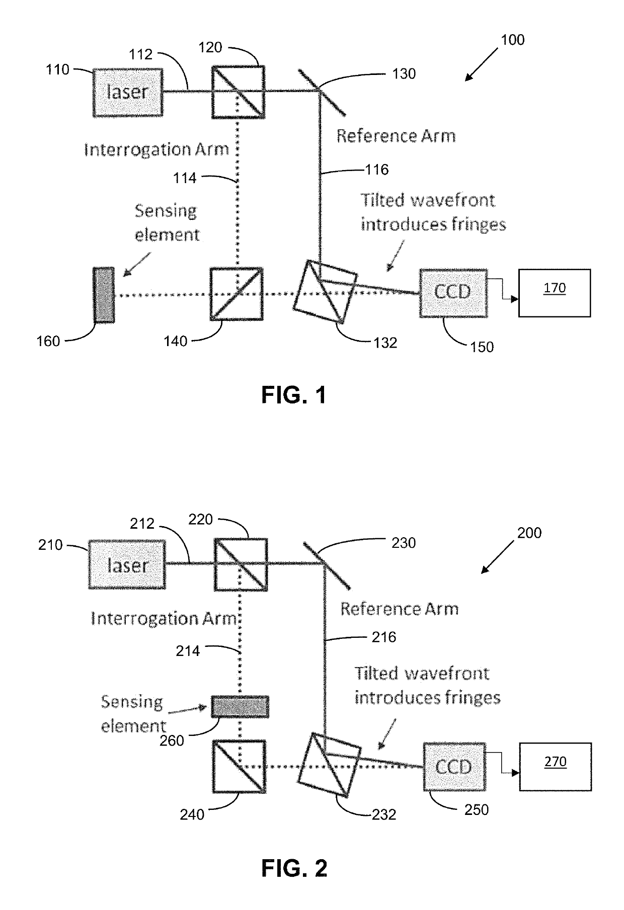
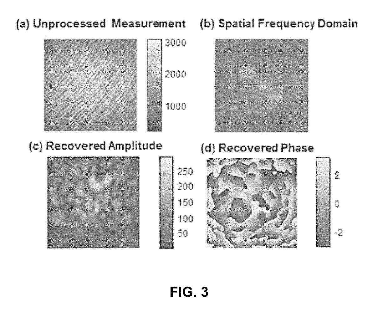
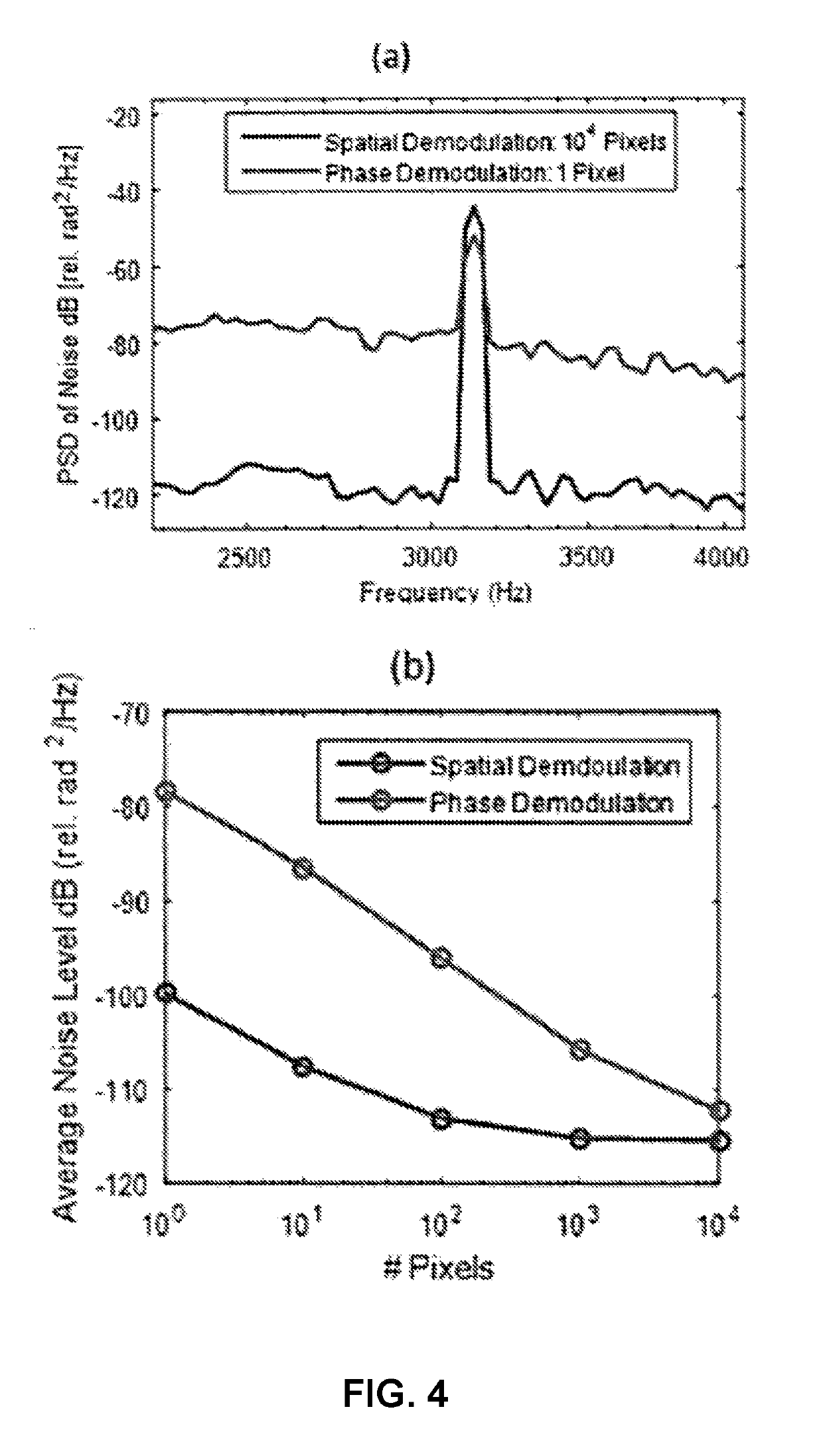
[0033]A wide range of optical sensing systems rely on the precise measurement of the optical phase delay of an interrogation beam. Exemplary embodiments of the invention measure the optical phase using a spatial demodulation scheme based on off-axis holography, resulting in significant advantages in terms of both sensitivity and bandwidth. Off-axis holography relies on a digital camera to record the interference pattern formed between the interrogation beam and a reference beam which are combined at a fixed angle (hence the name “off-axis”). The optical phase of the interrogation beam is recovered through the spatial Fourier transform of this interference pattern, enabling single shot phase measurements without the need for a carrier frequency as in phase and frequency demodulation schemes. In this technique, incoherent noise is spread over all of the camera pixels, enabling a noise level reduction proportional to the number of pixels. For existing high speed megapixel cameras, this...


PUM


Abstract

A method of interferometric optical sensing via spatial demodulation includes emitting a laser beam; splitting the laser beam into a reference beam and an interrogation beam; converting a desired signal into a change in the optical path of the interrogation beam via an optical sensor; and capturing the reference beam and the interrogation beam via a camera, wherein the interrogation beam is incident to the camera at a first angle and the reference beam is incident to the camera at a second angle different from the first angle, thereby causing an interference pattern at the camera.

Description

RELATED APPLICATIONS[0001]This application claims the benefit of U.S. Provisional Application No. 62 / 324,010 filed Apr. 18, 2016, which is hereby incorporated herein by reference.FIELD OF INVENTION[0002]The present invention relates generally to optical sensing, and more particularly to spatial demodulation in interferometric optical sensing.BACKGROUND[0003]A wide range of optical sensing modalities rely on the ability to accurately measure the optical phase of an interrogating beam. This includes both fiber and free space sensors designed to measure a range of parameters which can be mapped to a change in the optical pathlength, including temperature, strain, pressure, acoustic signals, or magnetic fields. All of these systems rely on extracting the optical phase of an interrogation beam, and as a result, several methods have been developed to measure the phase. The most common techniques rely on either phase or frequency modulation and detection is performed using a single photode...

Claims


Application Information

Patent Timeline
IPC IPC(8): G01B9/02G01J9/02
CPCG01J9/02G01D5/266G01J2005/583G01J2009/0238
Inventor REDDING, BRANDON F.DAVIS, ALLEN R.KIRKENDALL, CLAY K.DANDRIDGE, ANTHONY
Owner UNITED STATES OF AMERICA
Why Eureka
Try Eureka