

Electronic component and electronic device
a technology of electronic components and electronic components, applied in the direction of visual indication, instruments, horology, etc., can solve the problems of difficult to create a sense of quality, particularly high quality, and design changes cannot be imparted by the design rendered in the layers of the photoelectric conversion device, so as to improve the appearance of an electronic component.
- Summary
- Abstract
- Description
- Claims
- Application Information
AI Technical Summary
Benefits of technology
Problems solved by technology
Method used
Image

Examples
embodiment 1
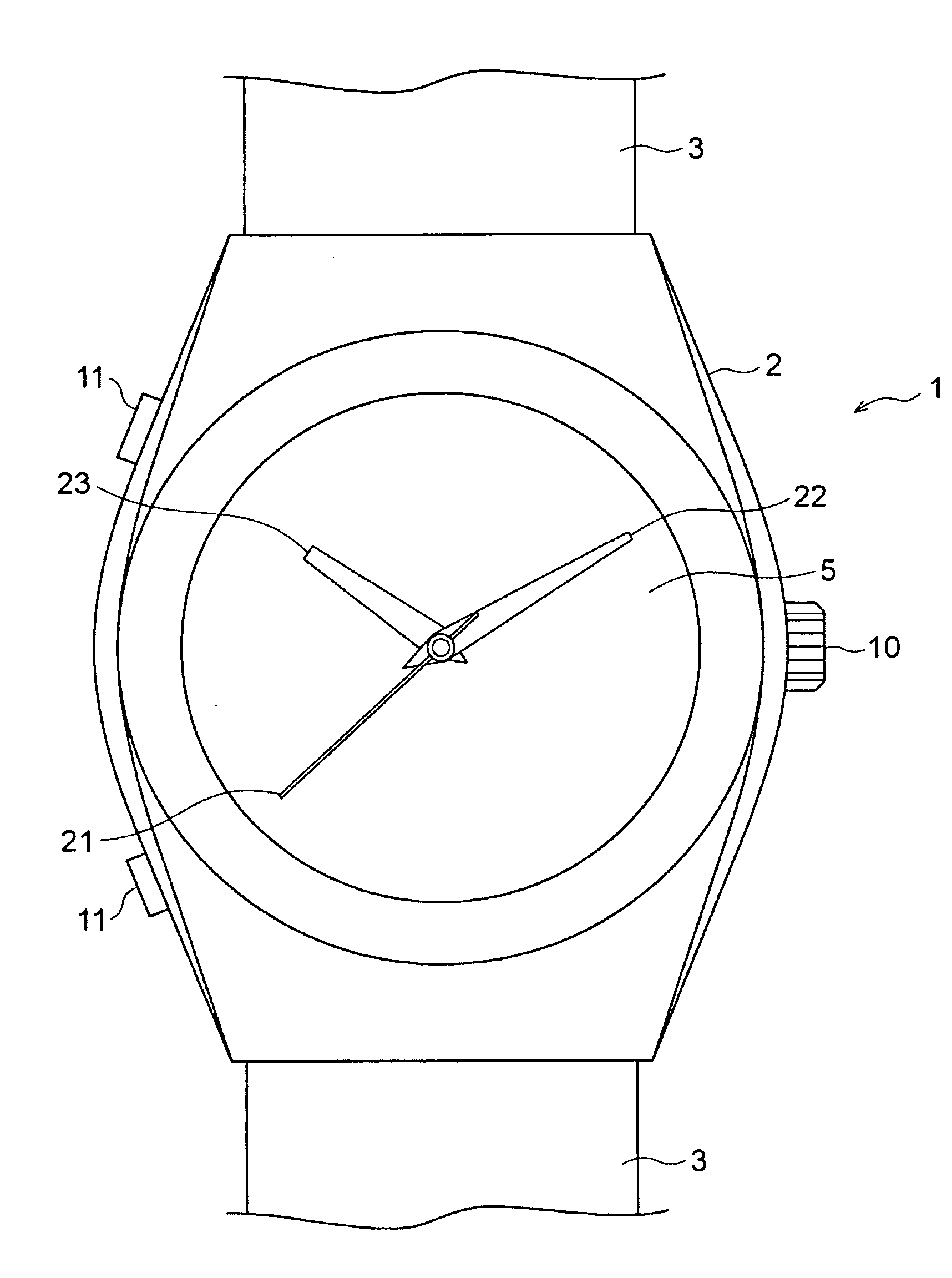
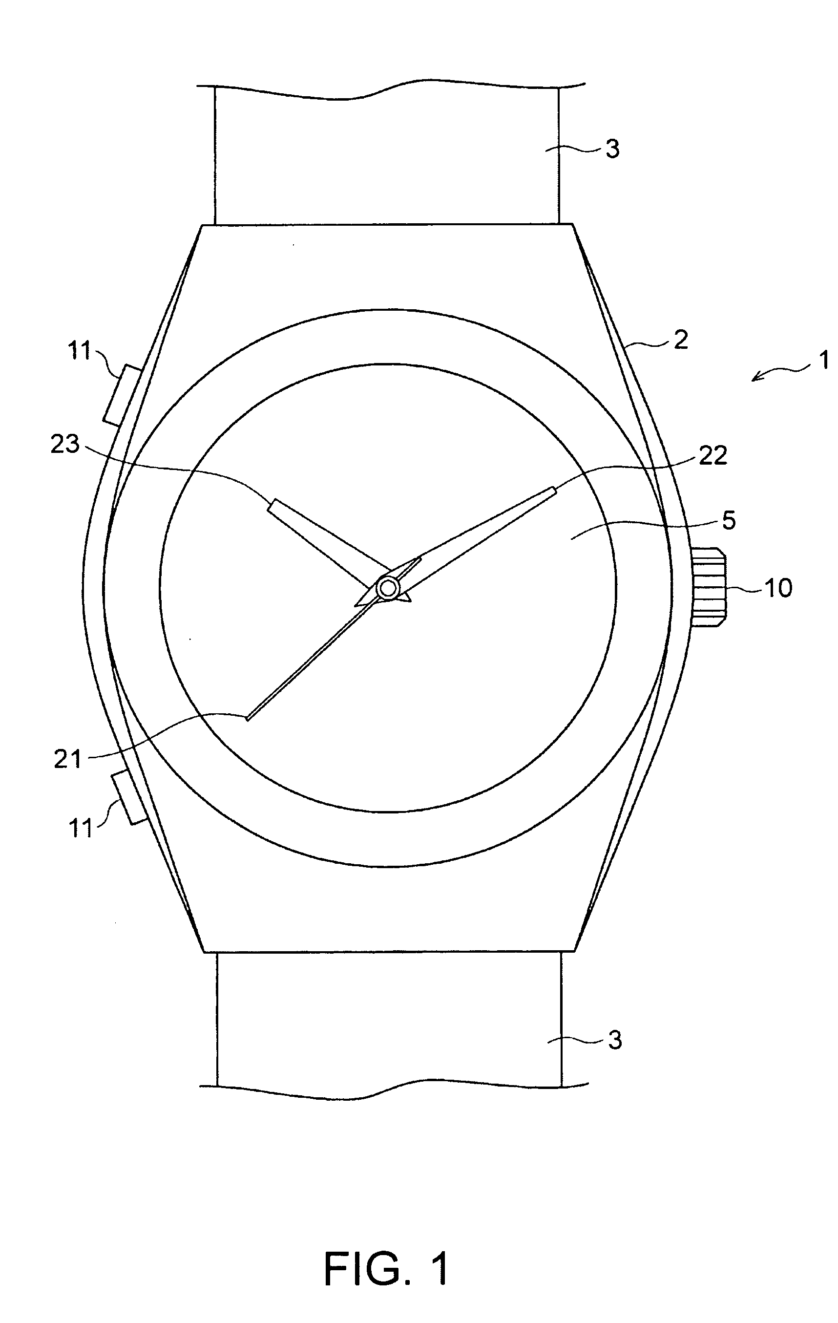
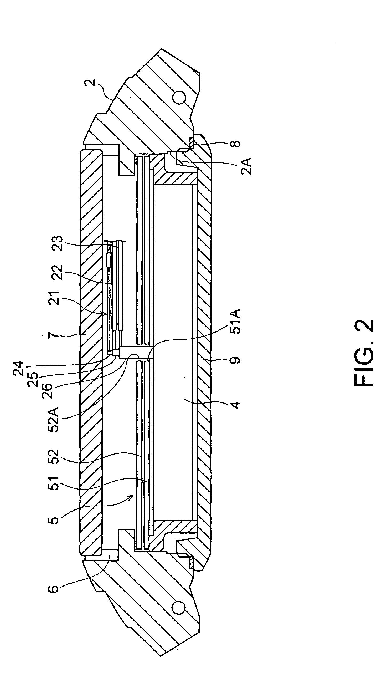
[0068]FIG. 1 is a front view of a wristwatch 1 according to a first embodiment of the invention. FIG. 2 is a side section view of this wristwatch 1. The wristwatch 1 has a watch case 2, and a wrist band 3 connected to the watch case 2. The watch case 2 is made of stainless steel or other metal, or from plastic or other synthetic material. As shown in FIG. 2, a through-hole 2A is rendered inside the watch case 2 for housing the movement 4 and a display unit 5 composing the dial.
[0069]A transparent glass or plastic crystal 7 is press fit with an intervening plastic or metal pressure ring 6 into one end (the face side) of the through-hole 2A in the watch case 2. A back cover 9 is screwed and secured with an intervening seal 8 to the other end (the back side of the timepiece) of the through-hole 2A. The back cover 9 and crystal 7 together seal the inside of the watch case 2.
[0070]A crown 10 and operating buttons 11 are disposed to the watch case 2 as shown in FIG. 1. The crown 10 is con...
second embodiment
[0107]FIG. 11 is an exploded oblique view showing the arrangement of the display unit 5 in a second embodiment of the invention, FIG. 12 is a section view of major parts in the second embodiment, and FIG. 13 is a plan view showing a view of the display unit 5.
[0108]The decorative member 53 disposed as ornamentation according to this second embodiment of the invention is a flat member rendered on the surface of the display panel 51 in the same way as the decorative member 52 described above. A multitude of intersecting lateral and longitudinal grooves (intersecting perpendicularly in this example) are formed in the surface of the decorative member 53. The interval between these grooves is constant, resulting in a matrix of substantially square trapezoidal pieces 53A arrayed on the surface of the decorative member 53.
[0109]As described above, the display panel 51 is a segment display panel. In this second embodiment of the invention the plural segments 51B are larger than in the first...
third embodiment
[0112]FIG. 14 is a section view showing the arrangement of the display unit 5 in a third embodiment of the invention. As shown in FIG. 14 a decorative member 54 having a multitude of whisker-like projections can be disposed for ornamentation on the surface of the display panel 51.
[0113]Whiskers having a fine diameter and pointed tip are arrayed on the surface of the decorative member 54. The surface of the decorative member 54 thus appears to be covered with hair. If a pattern (FIG. 8, FIG. 10) such as shown in the first or second embodiments is displayed on the display panel 51 using this decorative member 54, the appearance is significantly different from the surface of the display panel 51. In addition, an animated display can be achieved by continuously changing the image displayed on the display panel 51 so that the image, such as shown in FIG. 8 or FIG. 10, appears to move in a specific direction. By displaying images appropriate to the surface configuration of the decorative ...
PUM
 Abstract
Description
Claims
Application Information