
System and Method of Protecting Optical Cables

a technology of optical cables and protective devices, applied in the field of optical cables, to prevent excessive bending, prevent damage to the light carrying ability of optical fibers, and limit the amount of bending

Inactive Publication Date: 2008-05-29
ALCON INC
View PDF5 Cites 10 Cited by
  • Summary
  • Abstract
  • Description
  • Claims
  • Application Information

AI Technical Summary

Benefits of technology

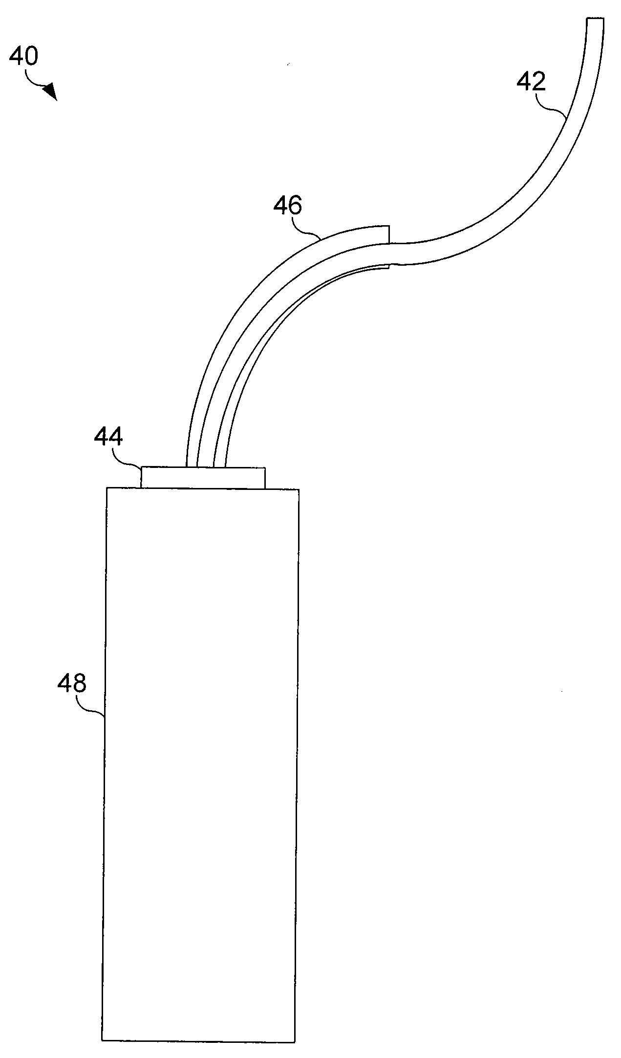
[0011]Embodiments of the present invention provide an optical connection that protects the optical fiber or cable. This optical connection includes an optical coupling to communicatively couple an optical fiber to an optical device. A mechanical guide receives the optical fiber proximate to the optical device. This mechanical guide prevents excessive bending or limits the amount of bending of individual optical fibers or cable proximate to the optical device. This may be achieved by receiving the optical fiber within a mechanical guide having a predetermined bend radius based on the optical fiber or optical cable running inside.
[0012]This type of optical connection may prevent damage to the optical fibers' light carrying abilities during the installation of static optical devices as well as inadvertent damage due to poor handling of portable optical devices. By limiting the potential for excessive bending of an optical fiber proximate to an optical coupling, the potential for attenuation within the fiber due to extreme bending is decreased.
[0013]Another embodiment of the present invention provides an optical device such as, but not limited, to a slit lamp, a laser source, or a second optical cable, wherein the optical device includes an optical coupling and a mechanical guide. The optical coupling optically and mechanically couples to a first optical cable, then the optical coupling allows light fed from or to the optical device to be handled internally within the optical device. The mechanical guide may be mounted on the optical device or may be mounted on the optical cable. In either case, this is done proximate to the optical coupling. The mechanical guide prevents excessive bending of the optical cable proximate to the device. For example, when the optical device is a second optical cable, mechanical guides at the optical coupling prevent excessive kinking and bending of the optical cables at the connection.
[0014]Yet another embodiment provides a method of coupling optical cables. This method involves optically coupling a first optical cable to an optical coupling. A mechanical guide may be coupled either to the optical coupling or a connector at the end of the first optical cable. In either case, the mechanical guide receives the optical cable and limits any bending thereof The optical coupling couples the optical cable to a second optical device. Excessive bending of the optical cable proximate to the optical device is prevented by limiting the bend radius of the optical cable within the mechanical guide.

Problems solved by technology

This type of optical connection may prevent damage to the optical fibers' light carrying abilities during the installation of static optical devices as well as inadvertent damage due to poor handling of portable optical devices.

Method used


Image

  • System and Method of Protecting Optical Cables
  • System and Method of Protecting Optical Cables
  • System and Method of Protecting Optical Cables

Examples


Embodiment Construction

[0025]Preferred embodiments of the present invention are illustrated in the FIGUREs, like numerals being used to refer to like and corresponding parts of the various drawings.

[0026]Embodiments of the present invention protect optical cables and optical connections by providing a protective mechanical guide that protects the optical cable and fiber therein from excessive bending. This guide facilitates the ability to optically and mechanically couple the optical fibers to an additional optical device. For example, an optical fiber may be connected to a slit lamp when the optical fiber is used to provide laser light from the slit lamp to its intended destination.

[0027]FIG. 3 shows an optical fiber 10 inside a loose tube 30. This arrangement allows the optical fiber 10 to be isolated from movement in the rest of the cable. Because the optical fiber 10 is not connected to the tube 30, the optical fiber 10 will follow a gently meandering path through the tube 30 and in so doing provide s...


PUM


Abstract

Embodiments of the present invention provide an optical connection that protects the optical fiber or cable. This optical connection includes an optical coupling to communicatively couple an optical fiber to an optical device. A mechanical guide receives the optical fiber proximate to the optical device. This mechanical guide prevents excessive or limits the amount of bending of individual optical fibers or cable proximate to the optical device. This may be achieved by receiving the optical fiber within a mechanical guide having a predetermined bend radius based on the optical fiber or optical cable running inside. By limiting the potential for excessive bending of an optical fiber proximate to an optical coupling the potential for attenuation of the transmitted light within the fiber due to extreme bending is decreased.

Description

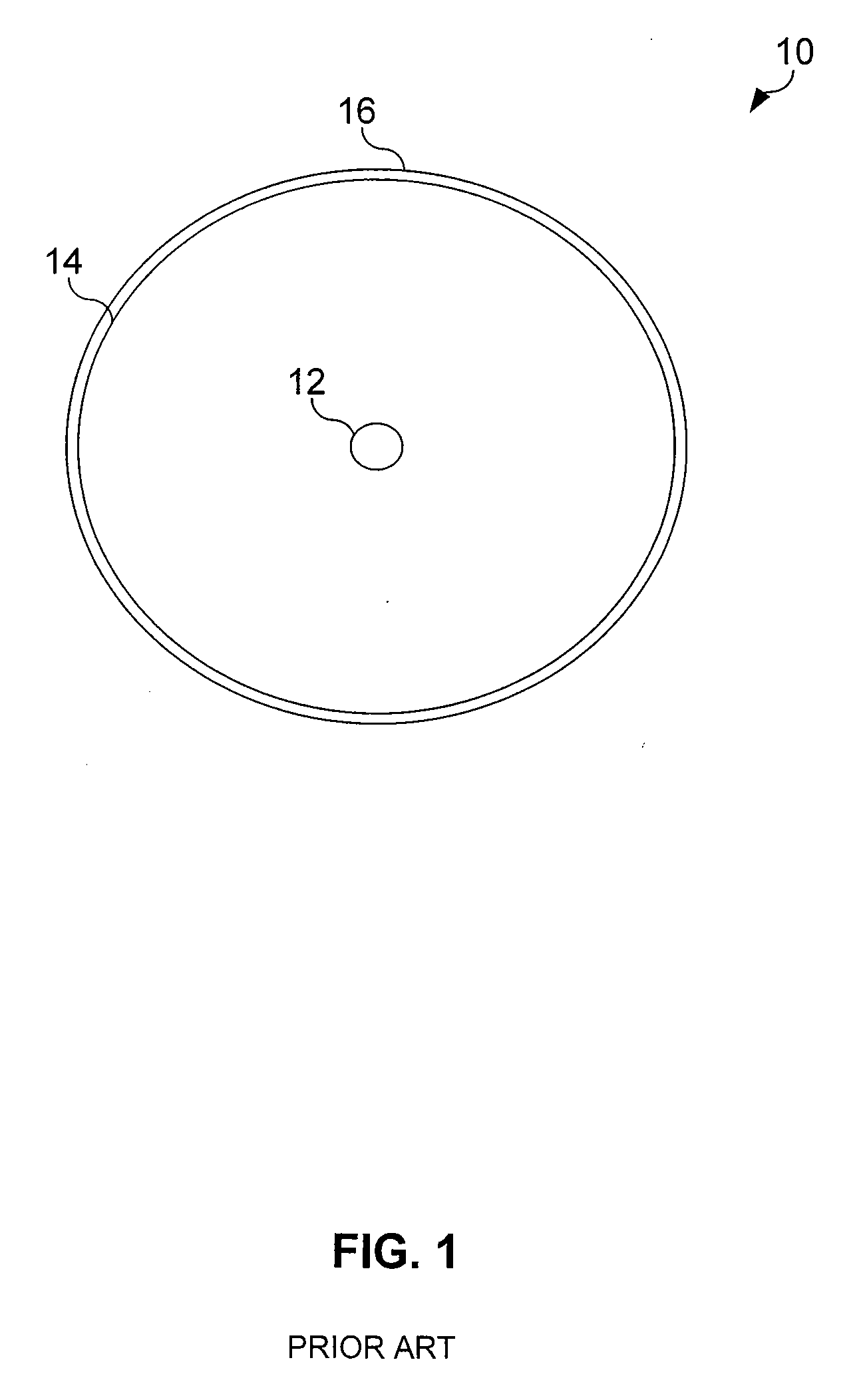
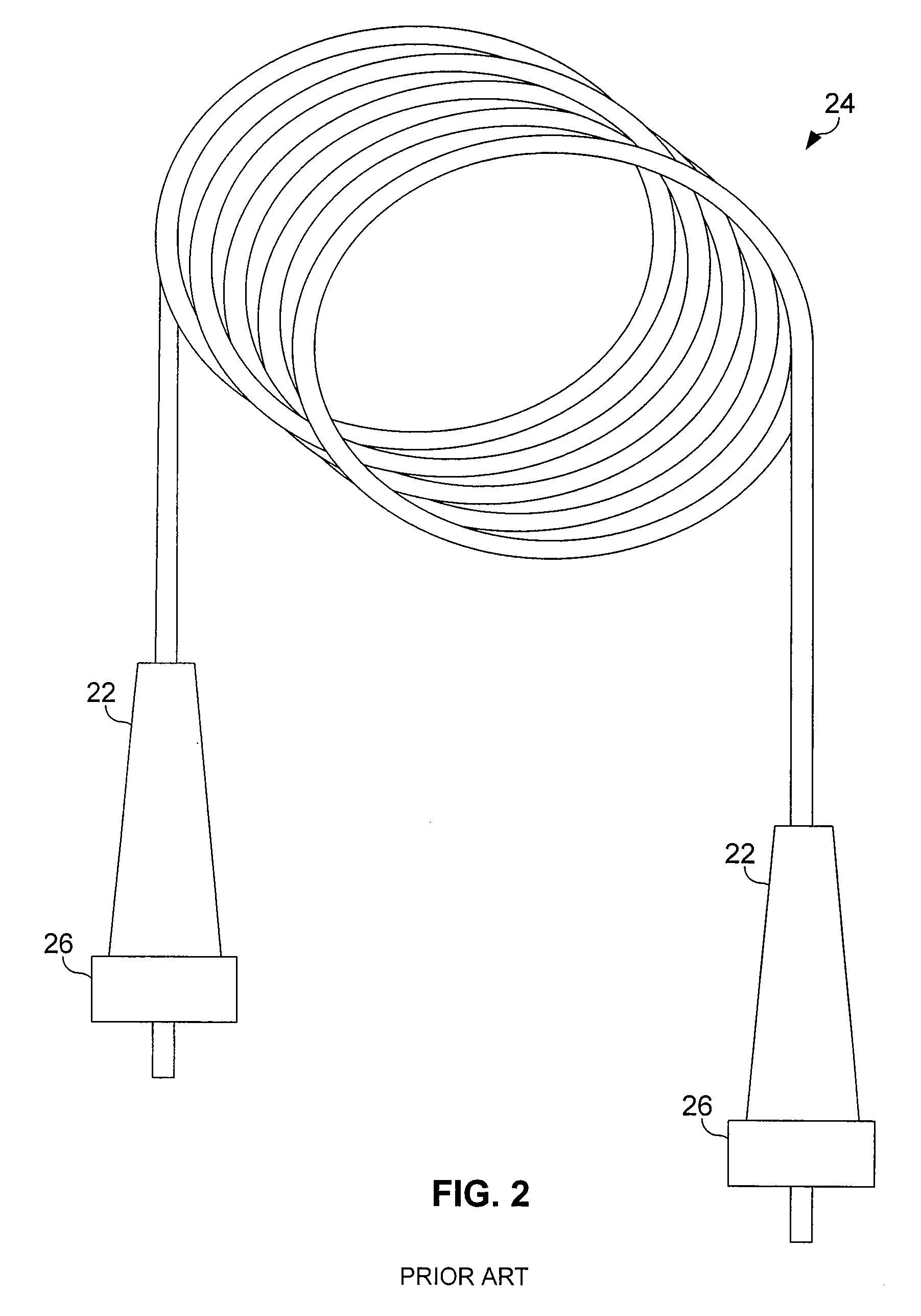
CROSS REFERENCE TO RELATED APPLICATION[0001]This application claims priority under 35 U.S.C. § 119 to U.S. Provisional Patent Application No. 60 / 795,737 filed Apr. 28, 2006, the entire contents of which are incorporated herein by reference.TECHNICAL FIELD OF THE INVENTION[0002]The present invention relates generally to optical cables, and more particularly, to a system and method of protecting an optical cable coupled to a device.BACKGROUND OF THE INVENTION[0003]Optical cables, which may include one or more optical fibers, are used in a wide variety of applications. These optical pathways may be used to carry large volumes of data over great distances, for example, or to efficiently transmit light from a light source to an area of interest. Optical fibers and cables are produced using precision manufacturing techniques and require exacting standards. Optical fiber can be thought of as a finely tuned instrument requiring care in production, handling, installation and use.[0004]FIG. 1...

Claims


Application Information

Patent Timeline
Patent Type & Authority Applications(United States)
IPC IPC(8): G02B6/44
CPCG02B6/4478
Inventor HORVATH, CHRISTOPHERLASSALAS, BRUNO X.
Owner ALCON INC
Learn More