Calibration Method To Achieve Reciprocity Of Bidirectional Communication Channels

a bidirectional communication channel and reciprocity technology, applied in the field of reciprocity of bidirectional communication channels, can solve problems such as inability to achieve reciprocity, and achieve the effect of achieving reciprocity

Inactive Publication Date: 2008-05-29
TELEFON AB LM ERICSSON (PUBL)
View PDF5 Cites 38 Cited by
  • Summary
  • Abstract
  • Description
  • Claims
  • Application Information

AI Technical Summary

Benefits of technology

[0022]One advantage afforded by the present invention is, since reciprocity is ensured, that methods for optimizing coding and mapping at the transmitter which requires an accurate forward channel estimation, can be used.
[0023]The described methods have the additional advantage that it can be used for relative calibration between stations that cannot or don't communicate. A typical example is coherent combining based cooperative relaying.

Problems solved by technology

However, in realistic situations, given e.g. non-perfect transmitter-receiver chains, the reciprocity might not hold.

Method used


Image

  • Calibration Method To Achieve Reciprocity Of Bidirectional Communication Channels
  • Calibration Method To Achieve Reciprocity Of Bidirectional Communication Channels
  • Calibration Method To Achieve Reciprocity Of Bidirectional Communication Channels

Examples


first embodiment

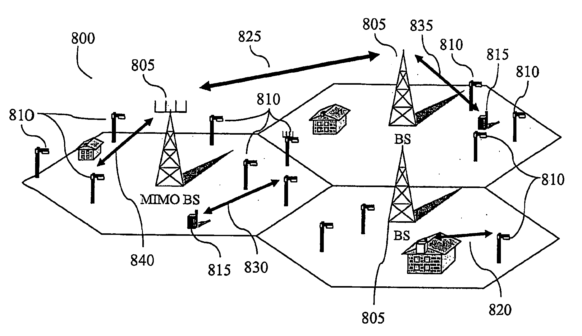
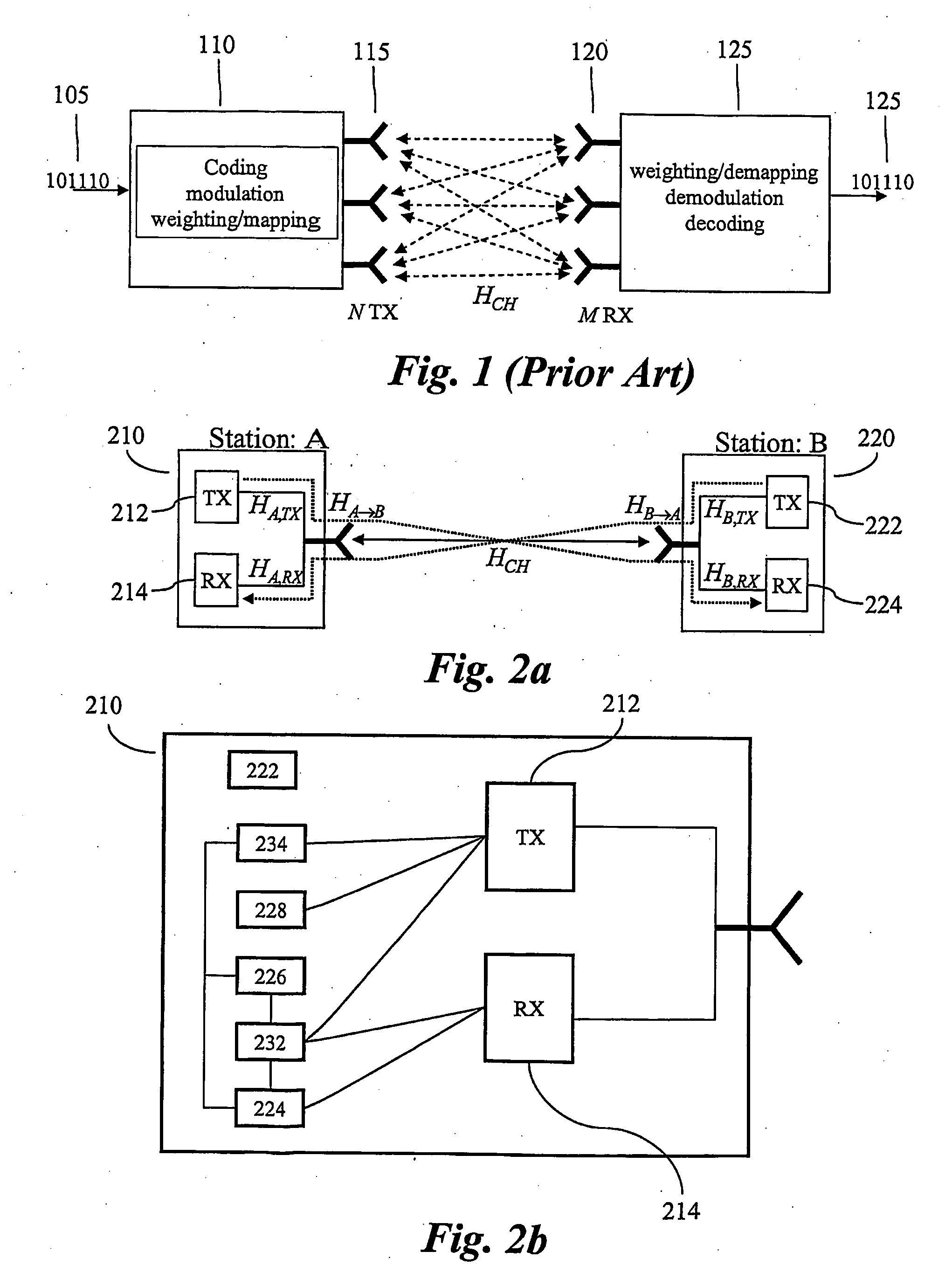
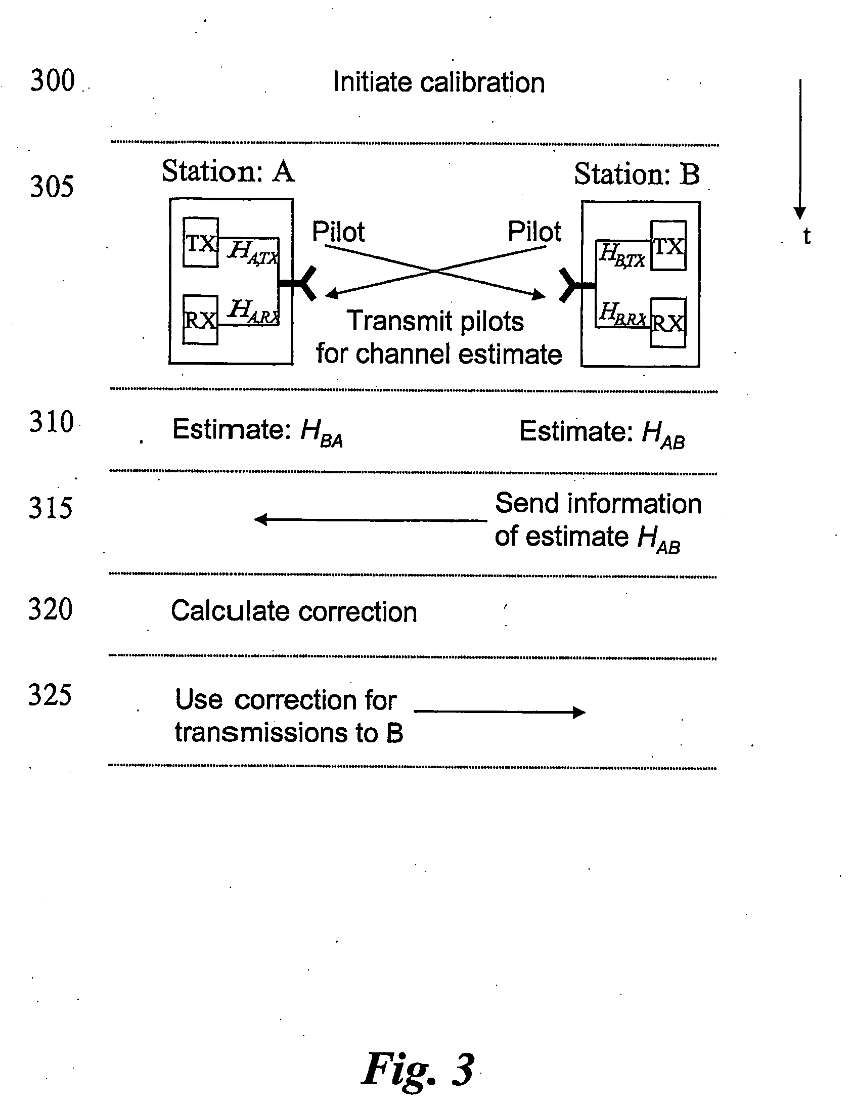
[0047]In the method according to the present invention, described with references to FIG. 4, channel estimation symbols are sent both from station A 210 to station B 220 and from station B to station A. Therefore estimates in both directions, ĤA→B and ĤB→A, can be produced (corresponding to step 310).

[0048]After the channel estimation the stations exchange its channel estimation data, e.g. station B send ĤA→B to station A (step 315). Based on ĤB→A already available at station A and the received ĤA→B, a channel correction factor can be determined (step 320) according to:

HCorr=H^B->AH^A->B=H^B,TX·H^CH·H^A,RXH^A,TX·H^CH·H^B,RX=H^B,TX·H^A,RXH^A,TX·H^B,RX(4)

[0049]A signal S, to be transmitted from A to B, is pre-multiplied with HCorr resulting in the received signal (step 325):

R=HA→B·HCorr·S+N   (5)

,where N is receiver noise. It is seen that the effective channel is modified into the reverse channel according to:

HA->B(eff)=HA->B·HCorr=HA,TX·HCH·HB,RX·H^B,TX·H^A,RXH^A,TX·H^B,RX≈HB,TX·HCH·...

second embodiment

[0058]In the method of the invention, described with references to the signalling scheme of FIG. 5, estimation symbols, or pilot, is transmitted in one direction only. In this embodiment, station A 210 first perform an open loop channel estimation by receiving a training symbol from station B. Based on the estimated channel, subsequent transmission form A to B is pre-multiplied with inverse of the channel estimate. Based on this, station B can report a correction factor back to station A. The correction factor is used for every transmission until next calibration instance. This is in essence a so called zero forcing scheme resulting in proportionally larger power is assigned to frequencies (assuming a frequency selective channel and e.g. OFDM) with high attenuation Possibly, one may avoid using high attenuation frequencies.

[0059]The correction factor fed back can preferably be in the form of a low order complex polynomial (possibly with exponential functions for any delays) and henc...

third embodiment

[0070]In the method of the present invention, described with references to the signalling scheme of FIG. 6, special estimation symbols (or pilot channel) is used in addition to the existing common pilot channel, to estimate a correction vector.

[0071]In for example, a MIMO scenario in which station A has nA antennas and station B has nB antennas, the frequency responses of the transceiver chains can be represented by diagonal matrices with elements corresponding to the response between the baseband processor and a particular antenna. For example, HA,TX is an nA by nA diagonal matrix and the channel's response is now an nB by nA matrix as seen by station B.

[0072]Following the example of calibrating station A through station B, similar to the first two embodiments, the channels from station A to station B can be estimated by station B through a known signal (a frequency domain column vector of dimension nA) generally referred to as the common pilot channel and here denoted by Pc. The a...


PUM


Abstract

The present invention relates to a method and arrangement to enhance the communication performance in wireless communication systems. The method of the invention provides a method of calibrating at least one first radio node in a wireless communication network. The communication network comprises at least a first radio node and a second radio node, which can be arranged to be in radio communication with each other. The calibration method is based on that at least one representation of radio channel characteristics, which has been exchanged from one radio node to the other. Whereby inaccuracies and differences in transmit receive chains are compensated and channel reciprocity can be used.

Description

FIELD OF INVENTION [0001]The present invention relates to a method and arrangement to enhance the communication performance in wireless communication systems. In particular, the present invention relates to the reciprocity of bidirectional communication channels.BACKGROUND OF THE INVENTION [0002]The demand for traffic capacity, coverage and reliability in the wireless communication systems is seemingly ever-increasing. One bottleneck in the traffic capacity is the limited frequency spectrum available for communication purposes, the limitation being both physical—only part of the frequency spectrum is suitable for communication and the information content per frequency and time is limited, and organisational—the useful part of the spectrum is to be used for a number of purposes including: TV and radio broadcast, non-public communication such as aircraft communication and military communication, and the established systems for public wireless communication such as GSM, third-generatio...

Claims


Application Information

Patent Timeline
Patent Type & Authority Applications(United States)
IPC IPC(8): H04Q7/20H04J99/00H04L25/02H04L25/03
CPCH04L25/0204H04L25/0224H04L25/0228H04L2025/03802H04L2025/03414H04L2025/03426H04L25/03343
Inventor LARSSON, PETERGUEY, JIANN-CHING
Owner TELEFON AB LM ERICSSON (PUBL)
Why Eureka
Try Eureka