
Method of controlling drive of driving motor for rotary indexing device of machine tool

a technology of rotary indexing device and driving motor, which is applied in the direction of process and machine control, process control, electric programme control, etc., can solve the problems of achieve the effect of effectively preventing the efficiency of processing from being degraded and reducing output torqu

Active Publication Date: 2008-05-29
TSUDAKOMA KOGYO KK
View PDF9 Cites 21 Cited by
  • Summary
  • Abstract
  • Description
  • Claims
  • Application Information

AI Technical Summary

Benefits of technology

The present invention provides a method for controlling the drive of a driving motor for a rotary indexing device of a machine tool. The method prevents processing failures and prevents the driving motor from becoming overload during control of the driving motor to a target rotational position. This is achieved by controlling the output torque of the driving motor with a content of control in which an output torque of the driving motor by position control becomes smaller than an output torque by position control during angular indexing for an equivalent positional deviation. The method reduces the output torque and prevents the driving motor from becoming overload state, even when the angular position of the circular table is deviated. This results in effective prevention of processing interruption and degradation of processing efficiency.

Problems solved by technology

Therefore, even when the angular position is deviated, processing is not interrupted due to the deviation, thereby effectively preventing the efficiency of processing from being degraded.

Method used


Image

  • Method of controlling drive of driving motor for rotary indexing device of machine tool
  • Method of controlling drive of driving motor for rotary indexing device of machine tool
  • Method of controlling drive of driving motor for rotary indexing device of machine tool

Examples


Embodiment Construction

[0020]Embodiments of the present invention are described below with reference to the drawings.

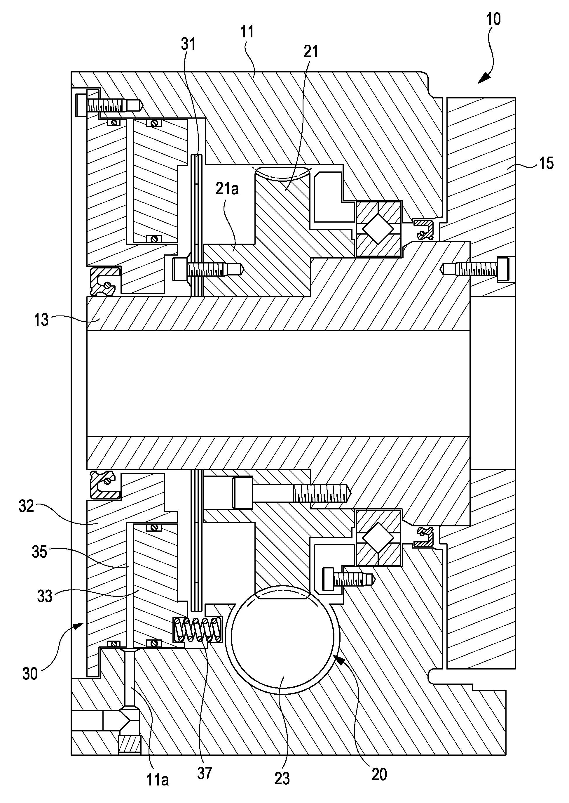
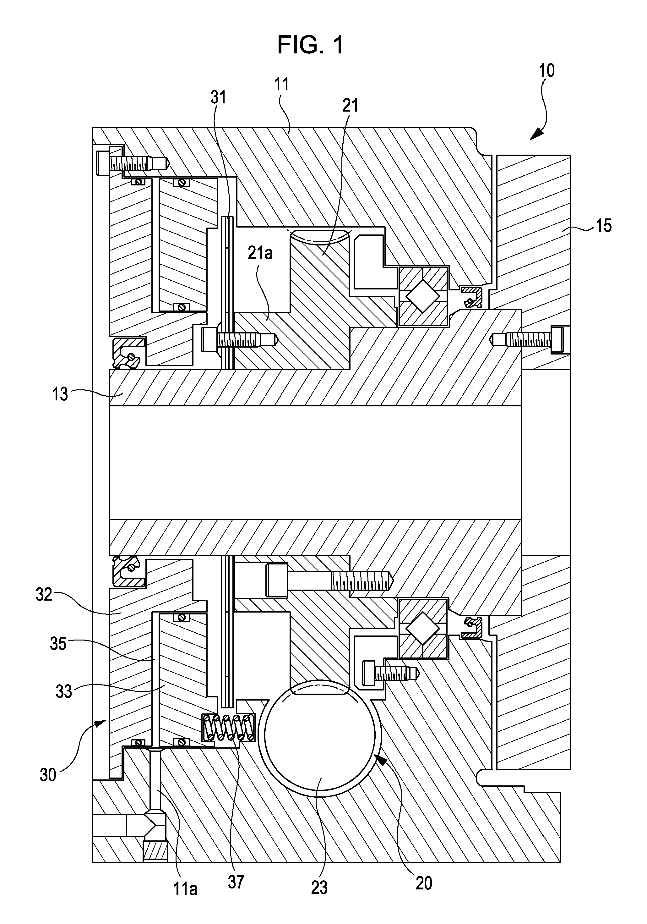
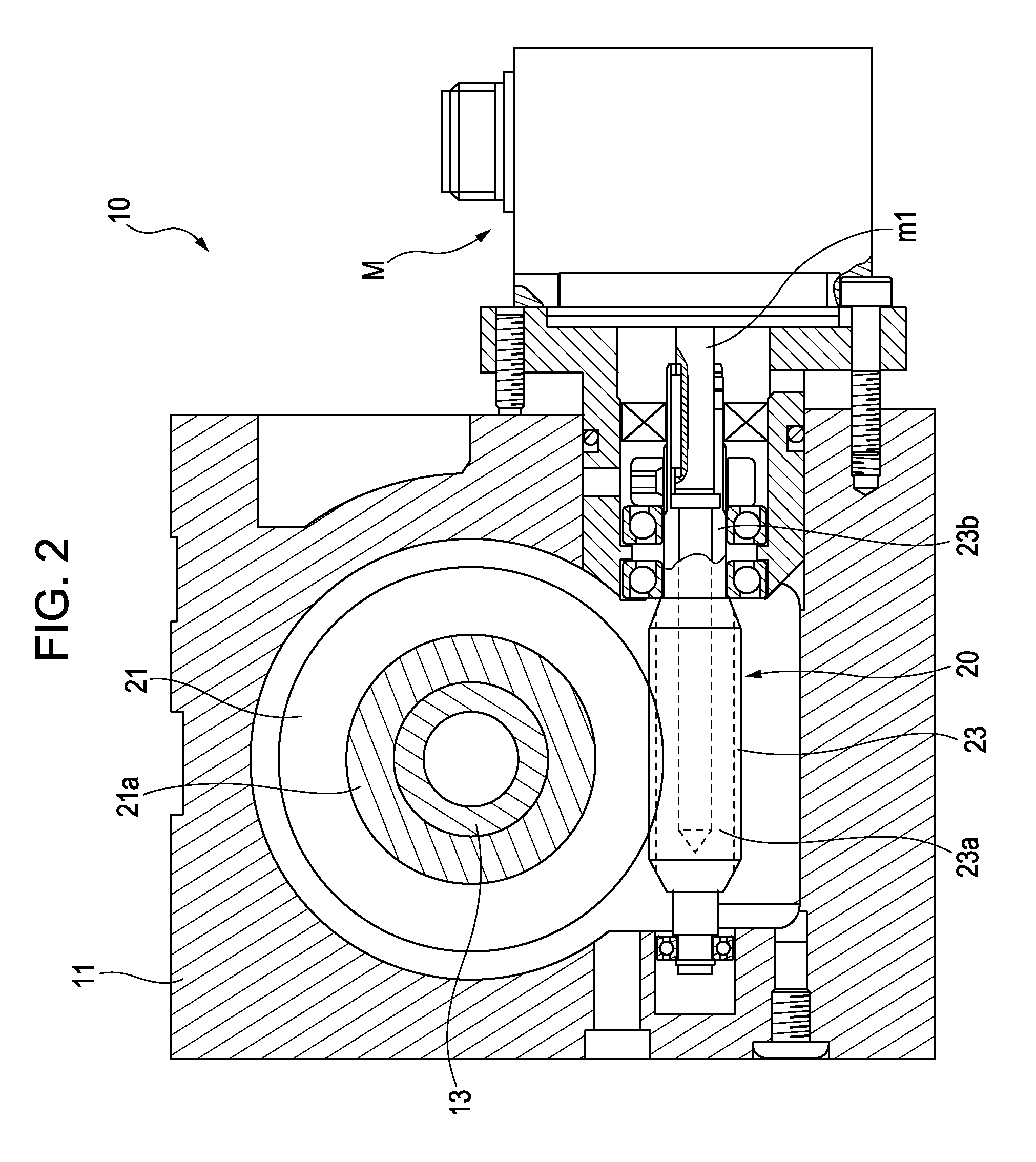
[0021]FIGS. 1 to 4 each show an embodiment of the present invention. FIGS. 1 and 2 each illustrate an index table 10 as a rotary indexing device of a machine tool to which the present invention is applied. The index table 10 includes a main shaft 13, a circular table 15, an indexing mechanism 20, and a clamping mechanism 30. The main shaft 13 is rotatably supported by a frame 11 with a bearing interposed therebetween. The circular table 15 is fixed at an end of the main shaft 13 by a plurality of screws arranged in a circumferential direction. The indexing mechanism 20 indexes the angular position of the circular table 15 by rotating the main shaft 13. The clamping mechanism 30 holds the indexed angular position of the circular table 15.

[0022]In the illustrated embodiment, the indexing mechanism 20 employs a worm gear mechanism. The indexing mechanism 20 has a worm wheel 21 fixed to the mai...


PUM

PropertyMeasurementUnit
torqueaaaaaaaaaa
clamping forceaaaaaaaaaa
forceaaaaaaaaaa

Abstract

A method of controlling drive of a driving motor for a rotary indexing device is provided. The device includes an indexing mechanism that indexes an angular position of a circular table by rotating the circular table with the use of the driving motor as a driving source, a clamping mechanism that holds the indexed angular position, and a control unit that controls drive of the driving motor by position control. In the method, the control unit controls the drive of the driving motor during operation of the clamping mechanism with a content of control in which an output torque of the driving motor by the position control becomes smaller than an output torque by the position control during indexing of the angular position of the circular table for an equivalent positional deviation.

Description

BACKGROUND OF THE INVENTION[0001]1. Field of the Invention[0002]The present invention is applied to angular indexing devices of machine tools, or to a rotary indexing device including an indexing mechanism that indexes an angular position of a circular table by rotating the circular table with the use of a driving motor as a driving source, a clamping mechanism that holds the indexed angular position, and a control unit that controls drive of the driving motor by position control. In particular, the present invention relates to a method of controlling the driving motor during operation of the clamping mechanism of the rotary indexing device.[0003]2. Description of the Related Art[0004]For example, Japanese Unexamined Patent Application Publication No. 10-29125 discloses a rotary indexing device of a machine tool to which the present invention is applied. The rotary indexing device disclosed in the publication has a table (circular table) rotatably supported at a base, and an indexin...

Claims


Application Information

Patent Timeline
Patent Type & Authority Applications(United States)
IPC IPC(8): G06F19/00B23B7/04B23Q15/00B23Q16/02G05B19/19
CPCG05B19/402Y10T74/1494Y10T29/5155Y10T74/1488Y10T74/1435B23Q16/00B23Q17/20
Inventor OSAKI, HARUOYONENAGA, TAKESHI
Owner TSUDAKOMA KOGYO KK
Learn More