Heat sink assembly having a fan mounting device

Inactive Publication Date: 2008-06-05
HON HAI PRECISION IND CO LTD
View PDF13 Cites 14 Cited by
  • Summary
  • Abstract
  • Description
  • Claims
  • Application Information

AI Technical Summary

Benefits of technology

[0007]Accordingly, what is needed is a heat sink assembly having a fan holder for facilitating firm fastening of a fan to a heat sink.

Problems solved by technology

Such heat can adversely affect the operational stability of the computers.
However, the process of forming the threaded holes 16a is unduly time-consuming and raises production costs.
Furthermore, in operation, the screws 70a are prone to be loosened by vibration and make noise.

Method used


Image

  • Heat sink assembly having a fan mounting device
  • Heat sink assembly having a fan mounting device
  • Heat sink assembly having a fan mounting device

Examples


Embodiment Construction

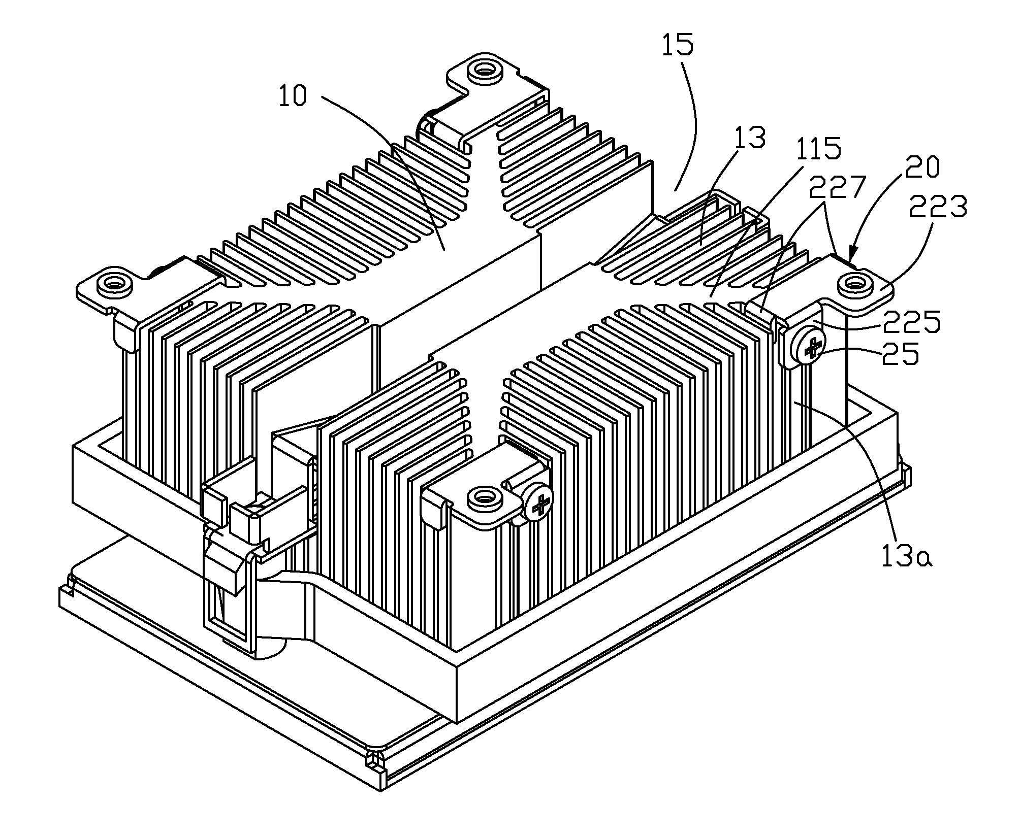
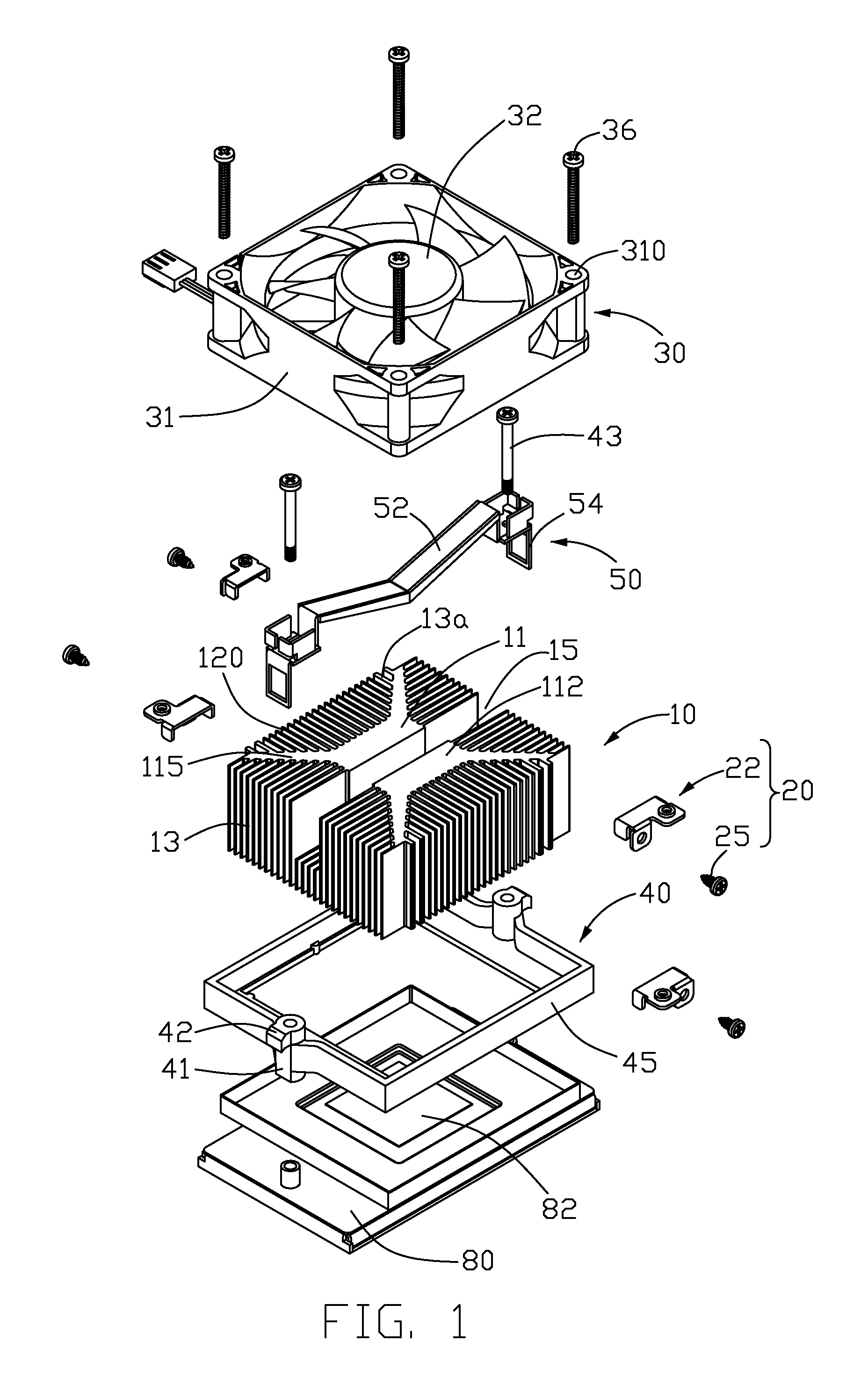
[0015]FIG. 1 illustrates a heat sink assembly in accordance with a preferred embodiment of the present invention. The heat sink assembly is configured (i.e., structured and arranged) for dissipating heat from an electronic component, such as a CPU 82 on a circuit board 80, comprising a heat sink 10, a plurality of fasteners 20, a fan 30 mounted on the heat sink 10 via the fasteners 20, a mounting seat 40 on the circuit board 80, and a clip 50 for fixing the heat sink 10 in the mounting seat 40 in such a manner that the heat sink 10 contacts the CPU 82.

[0016]The mounting seat 40 is a rectangular frame, comprising four sidewalls 45 surrounding an opening within which the CPU 82 is located. Two columns 41 are formed on two opposite sidewalls 45 of the mounting seat 40. The mounting seat 40 is fixed to the circuit board 80 by two screws 43 passing through the columns 41 and extending into the circuit board 80. A protrusion 42 extends laterally and outwardly from an outer side of each co...


PUM


Abstract

A heat sink assembly comprises a heat sink (10) having a plurality of outwardly extending fins (13), a plurality of fasteners (20) and a fan (30) mounted on the heat sink (10) via the fasteners (20). Each of the fasteners (20) comprises a self-tapping screw (25) and a fan holder (22). The fan holder (22) is buckled on the fins (13) and comprises a retaining body (220). The retaining body (220) of each fan holder (22) spans cross each corner of the heat sink (10). A connecting portion (225) extends downwardly from the retaining body (220). The connecting portion (225) abuts against the fins (13) of the heat sink (10). Each self-tapping screw (25) is inserted into a hole (228) defined in the connecting portion (225) and a space between two adjacent fins (13a) of the heat sink (10) to attach the fan holder (22) to the heat sink (10).

Description

CROSS-REFERENCES TO RELATED APPLICATION[0001]This application is related to U.S. patent application Ser. No. 11 / 164,095 filed on Nov. 22, 2005 and entitled “HEAT SINK ASSEMBLY HAVING A FAN MOUNTING DEVICE”; the co-pending U.S. patent application is assigned to the same assignee as the present application. The disclosure of the above-identified application is incorporated herein by reference.BACKGROUND OF THE INVENTION[0002]1. Field of the Invention[0003]The present invention relates generally to a heat sink assembly, and particularly to a heat sink assembly for cooling an electronic element such as a CPU by the use of a heat sink which is mounted with a fan via a fan holder.[0004]2. Description of Related Art[0005]A computer central processing unit (CPU) is the core controlling unit of electrical signals in most contemporary personal computers. Continued development of CPUs has enabled them to perform more and more functions. Heat generated by the CPUs has increased enormously. Such...

Claims


Application Information

Patent Timeline
IPC IPC(8): H05K7/20
CPCF28F3/02G06F1/20H01L23/4093H01L23/467H01L2924/0002H01L2924/00
Inventor LAI, CHENG-TIENLU, CUI-JUNLIU, SONG-SHUI
Owner HON HAI PRECISION IND CO LTD
Why Eureka
Try Eureka