Carrying Device, Recording Device, and Carrying Method

Inactive Publication Date: 2008-06-05
SEIKO I INFOTECH
View PDF12 Cites 11 Cited by
  • Summary
  • Abstract
  • Description
  • Claims
  • Application Information

AI Technical Summary

Benefits of technology

[0017]According to the carrying device of the present invention structured as described above, the support tube wound with the recording material is supported at a position thereof corresponding to the central portion in the width direction of the recording material by the large-diameter portion of the roll shaft, thereby suppressing the central portion in the width direction of the recording material wound around the support tube from being bent in a state where the support roll is supported by the

Problems solved by technology

This leads to deterioration in quality of images or the like recorded on the recording material.
Further, there is a problem in that the recording material, which is carried while being wrinkled, is partially floated from the platen, and a portion floated therefrom collides with the recording head.
As a result, it is likely to damage the recording head and to soil the recording material with ink droplets.
Therefore, there is a problem in that a size of the printer is increased toward the carrying direction.
Further, with the conventional printer, it is difficult to straighten and flatten the wrinkles occurred by being bent due to an own weight of the recording material.
Therefore, there is a problem in that in the supply roll, the recording material is curved inwardly at a central part in a width direction thereof due to the own weight of the recording material which has been wound, and is bent with respect to the width direction.
There is a disadvantage in that wrinkles easily occur on

Method used


Image

  • Carrying Device, Recording Device, and Carrying Method
  • Carrying Device, Recording Device, and Carrying Method
  • Carrying Device, Recording Device, and Carrying Method

Examples


Example

[0039]Hereinafter, a specific embodiment of the present invention will be described with reference to the drawings.

[0040]In an ink jet printer according to this embodiment, as a recording material, for example, a recording material formed of paper, a synthetic resin, or the like is used, the recording material having a relatively large width, that is, for example, a width dimension perpendicular to a carrying direction of about 2 m to 2.5 m. For the sake of convenience, a description will be made while taking a recording sheet as an example.

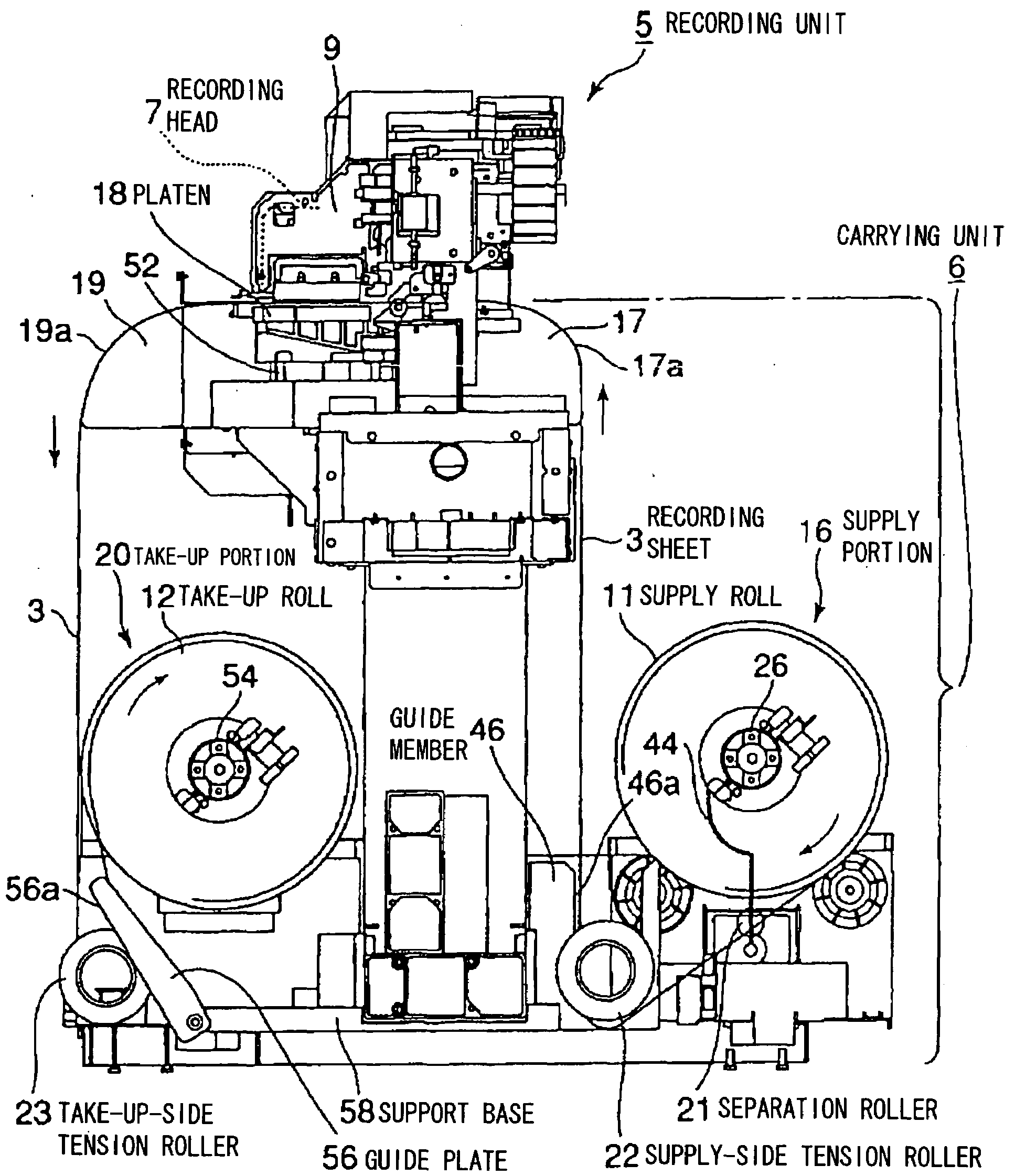
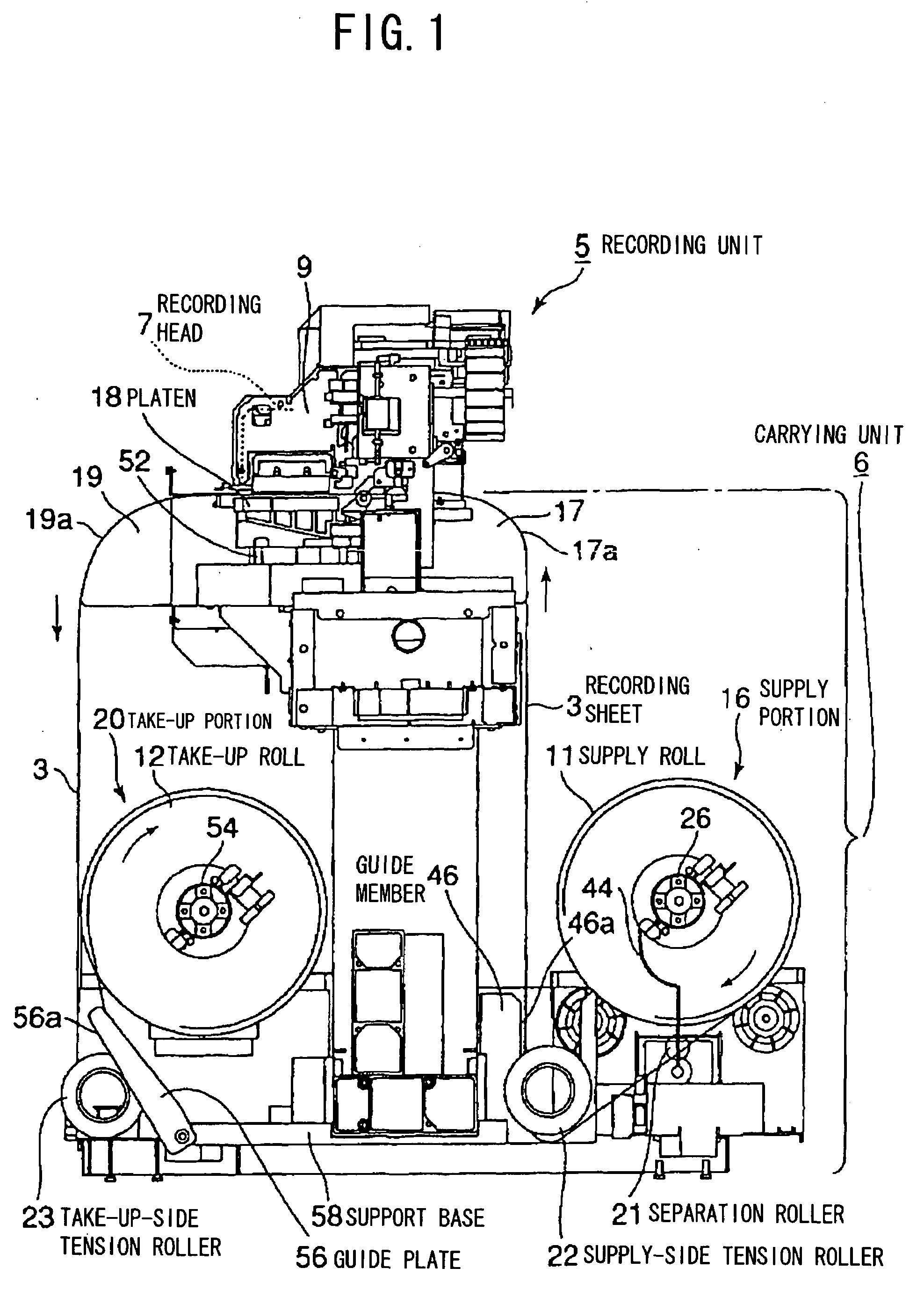
[0041]As shown in FIG. 1, the ink jet printer includes a recording unit 5 for performing recording on a recording sheet 3 and a carrying unit 6 for carrying the recording sheet 3 on which recording is performed by the recording unit 5.

[0042]The recording unit 5 includes, as shown in FIGS. 1 and 6, includes a recording head 7 for ejecting ink droplets onto the recording sheet 3 and a head moving mechanism 8 for allowing the recording head 7 to sca...


PUM


Abstract

A carrying device includes: a supply portion (16) for supplying a recording sheet (3) from a supply roll (11) wound with the recording sheet (3); a platen (18), which is opposed to a recording head (7) for performing recording on the recording sheet (3) supplied from the supply portion (16), for supporting the recording sheet (3); a take-up portion (20) in which the recording sheet (3) on which recording has been performed by the recording head (7) is taken up by a take-up roll (12); and a suction fan (52) for sucking the recording sheet (3) supported on the platen (18). The platen (18) is provided with, in a position corresponding to an area in which recording is performed by the recording head (7), a plurality of recessed portions (48), which are formed from an upstream side to a downstream side of the platen (18) in a carrying direction of the recording sheet (3) and are surrounded by projected walls (49), aligned in a width direction of the recording sheet (3). In bottom surfaces in the recessed portions (48), there are provided a plurality of suction holes (51) for sucking the recording sheet (3) by the suction fan (52). As a result, quality of recording by the recording head is increased by suppressing occurrence of wrinkles on a recording material which is carried.

Description

TECHNICAL FIELD[0001]The present invention relates to a carrying device for carrying a recording material when, for example, an image or the like is recorded on the recording material such as a recording sheet having a relatively large width, a recording device, and a carrying method.BACKGROUND ART[0002]Conventionally, there are known inkjet printers in which ink droplets are ejected onto a recording material such as a recording sheet to record characters, images, or the like. Among the ink jet printers described above, there are provided relatively large printers for performing recording on a recording material made of paper or vinylchloride, having a relatively large width; for example, a width of the recording material perpendicular to a carrying direction thereof is about 2 m to 2.5 m.[0003]The printer of this type includes a recording unit for performing recording on the recording material and a carrying unit for carrying the recording material on which recording is performed b...

Claims


Application Information

Patent Timeline
IPC IPC(8): B41J11/02B65H16/06
CPCB41J11/0085B41J11/06B41J15/04B65H2801/36B65H16/06B65H23/188B41J15/16
Inventor MIDORIKAWA, MASARU
Owner SEIKO I INFOTECH
Why Eureka
Try Eureka