Position controller for flexible substrate

a technology of lateral position controller and flexible substrate, which is applied in the direction of mechanical control devices, auxiliary welding devices, final product manufacturing, etc., can solve the problems of drooping flexible substrate, difficult to maintain constant conveying height, and wrinkles on the surface of flexible substrate, etc., to achieve the effect of suppressing drooping or wrinkles of flexible substrate and low cos

Inactive Publication Date: 2014-06-10
FUJI ELECTRIC CO LTD
View PDF13 Cites 0 Cited by
  • Summary
  • Abstract
  • Description
  • Claims
  • Application Information

AI Technical Summary

Benefits of technology

[0025]As described above, the position controller for flexible substrate according to the invention may effectively suppress drooping or wrinkles of the flexible substrate when performing a process such as film forming on the conveying band-shaped flexible substrate, maintaining the lateral position to be constant to perform a high-quality process thereon, and handling a reciprocating process including reverse conveying of the flexible substrate at low cost.

Problems solved by technology

However, when the conveying span is lengthened, it is difficult to maintain the conveying height to be constant against the gravity, and there is a noticeable tendency that wrinkles occur on the surface of the flexible substrate or the flexible substrate is drooped.

Method used


Image

  • Position controller for flexible substrate
  • Position controller for flexible substrate
  • Position controller for flexible substrate

Examples


first embodiment

(First Embodiment)

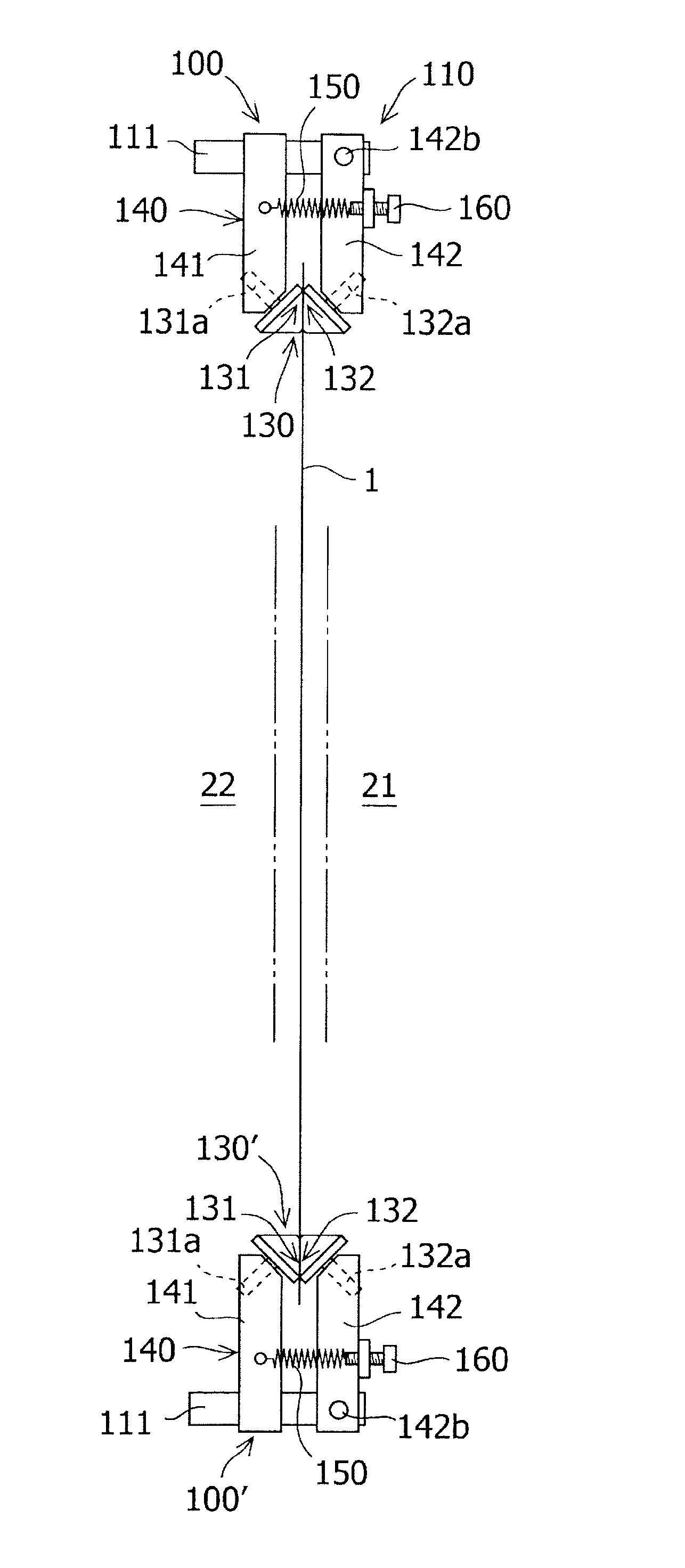
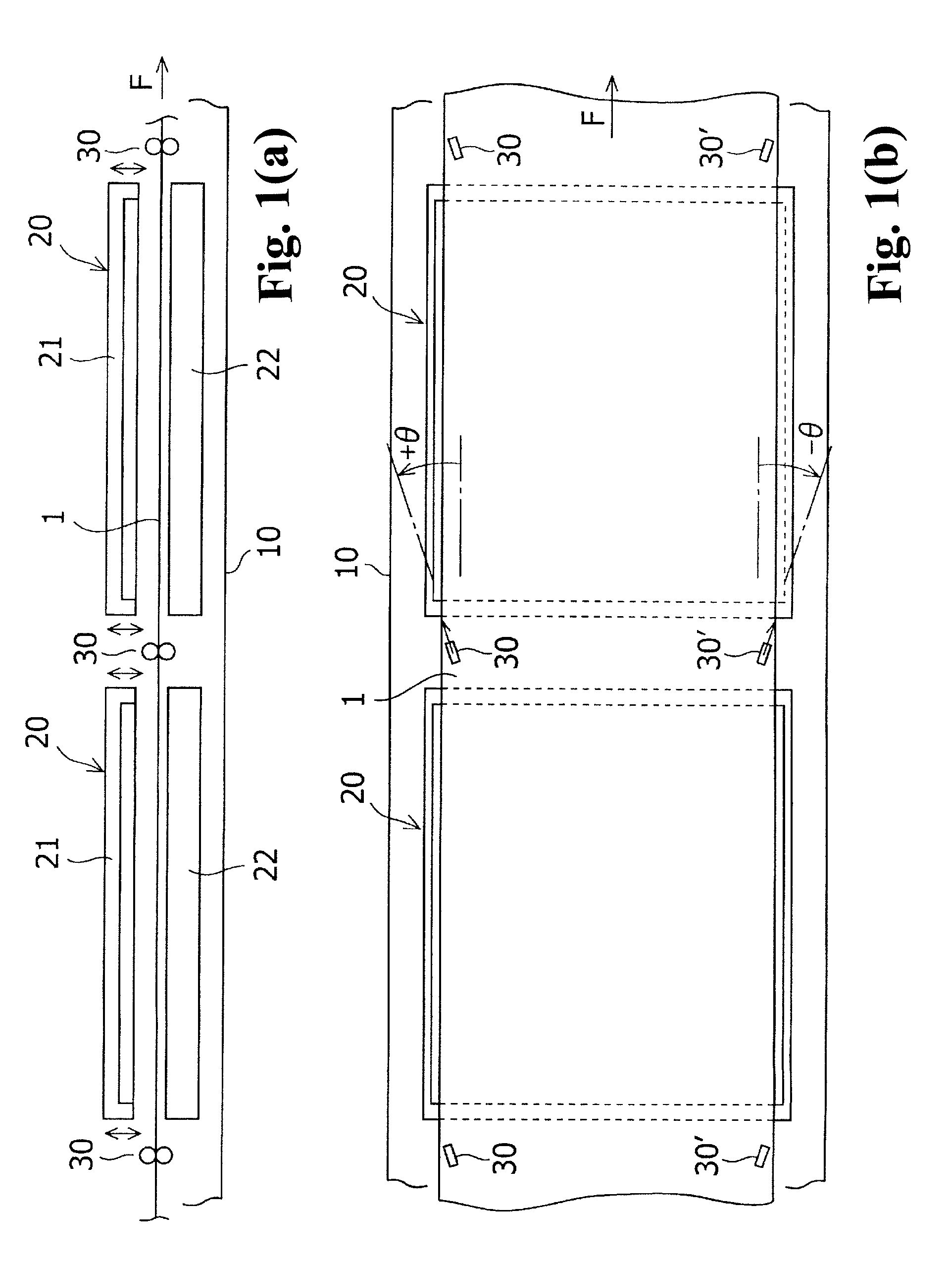
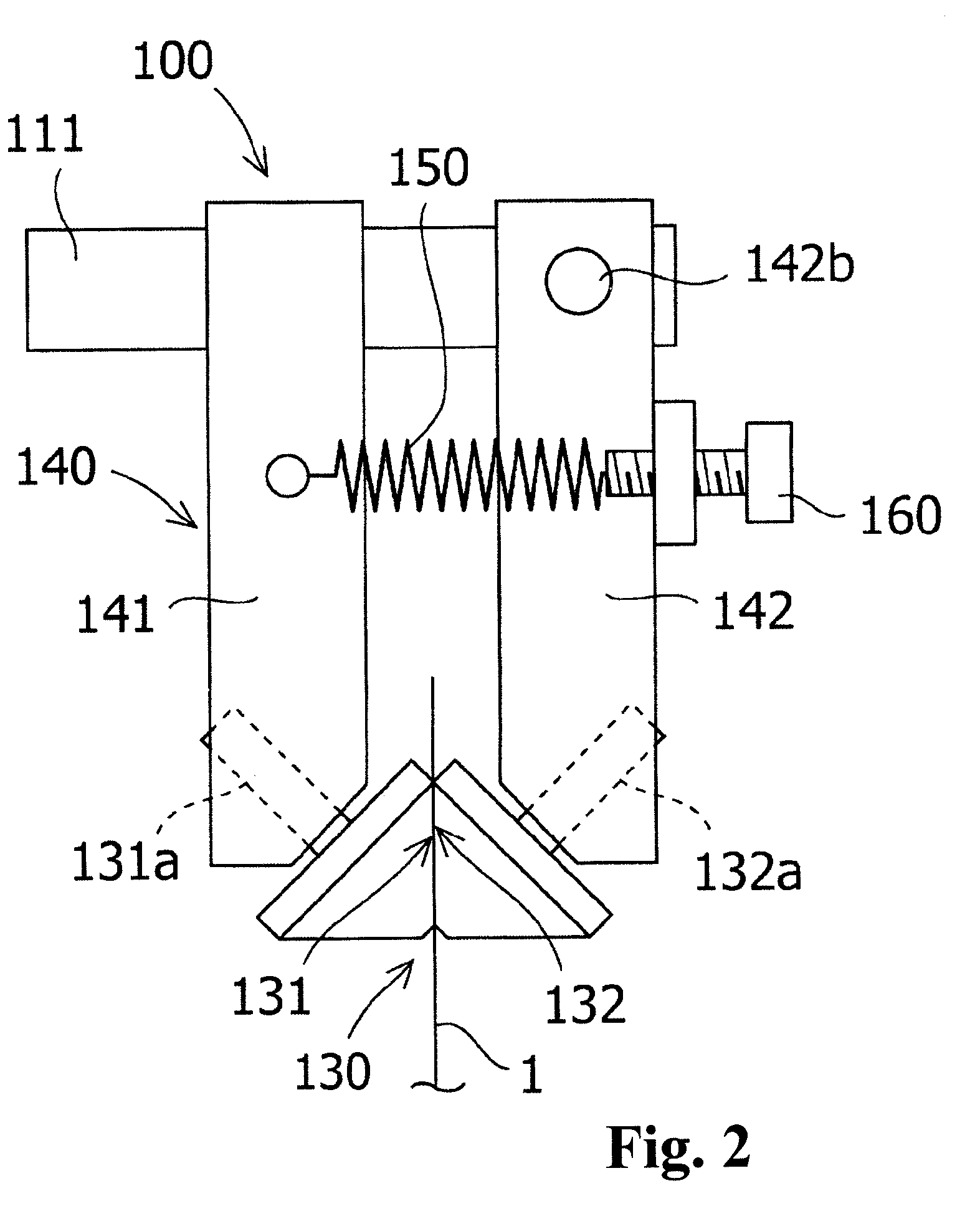
[0042]FIG. 2 is a front view illustrating a position controller for substrate 100 according to a first embodiment of the invention when seen from the upstream in the conveying direction. As partially shown in FIGS. 4A and 4B, the thin film laminated body manufacturing apparatus conveys a band-shaped flexible substrate 1 (flexible film) in the horizontal direction inside a vacuum chamber 10 maintained at a predetermined vacuum degree while taking a longitudinal position, that is, the lateral direction is set as the vertical direction, and laminates thin films on the surface of the flexible substrate 1 using a plurality of film forming units 20 (film forming portions) arranged in parallel along the conveying path of the flexible substrate 1.

[0043]Feeding roll or tension roll constituting a conveying unit of the flexible substrate 1 are disposed at the upstream and the downstream in the conveying direction of the film forming portion, and an unwinding roll and a windi...

second embodiment

(Second Embodiment)

[0064]FIG. 8 is a front view illustrating a position controller for substrate 200 according to a second embodiment of the invention when seen from the upstream in the conveying direction. In the position controller for substrate 200, sandwiching rollers 231 and 232 constituting a pair of sandwiching rollers 230 are all formed as truncated conical rollers. That is, in the sandwiching rollers 231 and 232 of the second embodiment, the shape of the large diameter side is the same as that of the sandwiching rollers 131 and 132 of the first embodiment, but the small diameter side is shortened. Since the other configurations are the same as those of the first embodiment, the same reference numerals are given thereto, and the specific description thereof will not be repeated. FIGS. 9A to 9C respectively correspond to FIGS. 3A to 3C.

[0065]In each of the sandwiching rollers 231 and 232 shown in the example shown in the drawing, the ratio of the width of the contact portion ...

third embodiment

(Third Embodiment)

[0075]FIG. 15 is a cross-sectional view illustrating an embodiment in which a position controller for substrate 300 which is the same as that of the second embodiment of the invention is applied to a continuous film forming type manufacturing apparatus 312 conveying a substrate in a lateral position when seen from the upstream in the conveying direction. In the thin film laminated body manufacturing apparatus 312, a film forming unit including an electrode 325 (target) and a ground electrode 326 disposed at the upper and lower sides to face each other with the flexible substrate 1 interposed therebetween is disposed inside a vacuum chamber maintained at a constant vacuum degree. Guide rolls (idle rolls), feeding rolls, tension rolls, or the like constituting a conveying unit are disposed at the upstream and the downstream in the conveying direction of the film forming unit, and an unwinding roll and a winding roll of the flexible substrate 1 are disposed at the ups...


PUM

PropertyMeasurementUnit
inclination angleaaaaaaaaaa

Abstract

Provided is a position controller for a flexible substrate (100) provided in a processing apparatus conveying a band-shaped flexible substrate (1) in a longitudinal position, in the lateral direction and processing the substrate in a processing unit (20) installed on a conveying path of the substrate. The position controller for the flexible substrate includes a pair of sandwiching rollers (131 and 132) that sandwiches an upper edge of the substrate; a supporting mechanism (140) that supports the pair of sandwiching rollers so as to be rotatable and movable close to or away from each other; an urging device (150) that applies a pressing force to the pair of sandwiching rollers through the supporting mechanism; and a pressing force adjusting device (160) adjusting the pressing force from the urging device, wherein each roller constituting the pair of sandwiching rollers is a conical roller having a circumferential surface inclined with respect to the axial direction, and is supported to the supporting mechanism so that a small diameter side of each conical roller is located at a center side of the substrate in the lateral direction and the rotation direction of a sandwiching surface of the substrate is the same as the conveying direction of the substrate.

Description

RELATED APPLICATIONS[0001]The present application is National Phase of International Application No. PCT / JP2010 / 072987 filed Dec. 21, 2010, and claims priorities from Japanese Application No. 2010-026502, filed Feb. 9, 2010 and Japanese Application No. 2010-162704, filed Jul. 20, 2010.TECHNICAL FIELD[0002]The present invention relates to a lateral position controller for a flexible substrate that is provided in an apparatus conveying a band-shaped flexible substrate and for performing a process such as film forming on the substrate in the conveying path thereof.BACKGROUND ART[0003]In general, a rigid substrate is used as a substrate of a thin film laminate of semiconductor thin films, but a flexible substrate such as a plastic film may be used in some cases for the purpose of improving productivity or reducing the cost because of the lightness and the easiness of handling attributed to the use of roll. Patent Literature 1 discloses a thin film laminated body manufacturing apparatus ...

Claims


Application Information

Patent Timeline
Patent Type & Authority Patents(United States)
IPC IPC(8): B32B37/00B29C65/00
CPCH01L21/67721C23C14/562H01L21/67259Y02E10/50H01L31/206C23C16/545H01L21/67706B29C66/95H01L21/6776B29C66/90Y10T156/17Y10T156/1741Y02P70/50
Inventor YAMADA, TAKANORIYOKOYAMA, SHOJI
Owner FUJI ELECTRIC CO LTD
Why Eureka
Try Eureka