Optical apparatus

Inactive Publication Date: 2008-06-05
ALPS ALPINE CO LTD
View PDF2 Cites 18 Cited by
  • Summary
  • Abstract
  • Description
  • Claims
  • Application Information

AI Technical Summary

Benefits of technology

[0033]The present invention provides a high-brightness, small, low-cost optical apparatus which covers a wide-angle to super-wide-angle region,

Problems solved by technology

However, the two-lens structure has, of course, a limited degree of design freedom, and it is difficult to increase the resolution or set an arbitrary projection method.
Therefore, the application of this optical apparatus is limited.
Therefore, although there is a relatively large degr

Method used


Image

  • Optical apparatus
  • Optical apparatus
  • Optical apparatus

Examples


examples

[0061]Next, examples of the present invention will be explained. In the examples, an optical surface of at least one lens is aspherical. The aspherical surface is defined by the following Expression 11. However, the present invention is not limited to this type.

z=ch21+1-(1+k)c2h2+A4h4+A6h6+A8h8+…+A26h26[Expression11]

[0062]In Expression 11, z shows the surface from the reference plane that passes through the vertex of the aspherical surface in the optical axes direction. In addition, c shows the reciprocal of the radius of curvature R of the surface, and h shows the height of the surface from the optical axis. In addition, k is the conical constant showing a second-order curve, and A4 to A26 are correction coefficients of the aspherical surface.

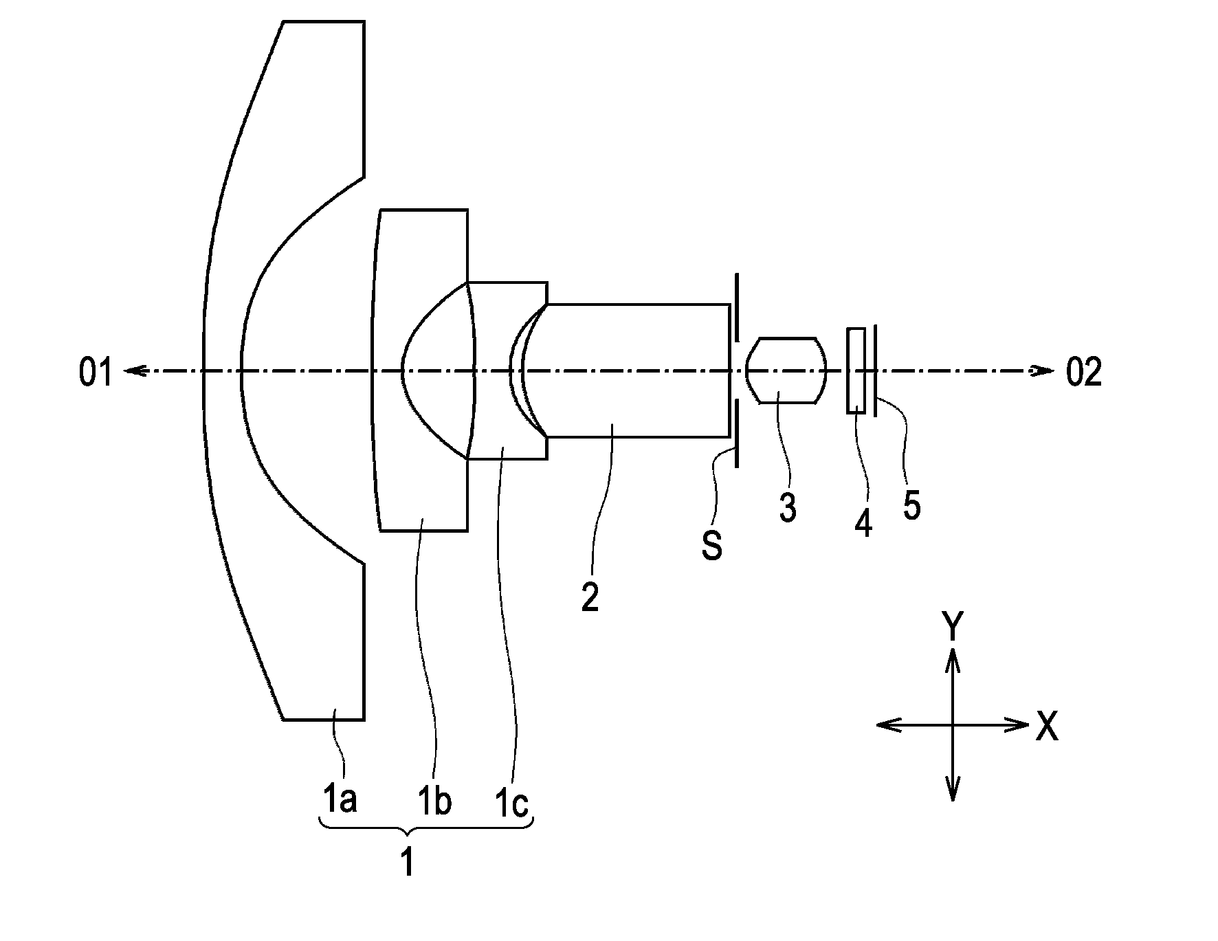
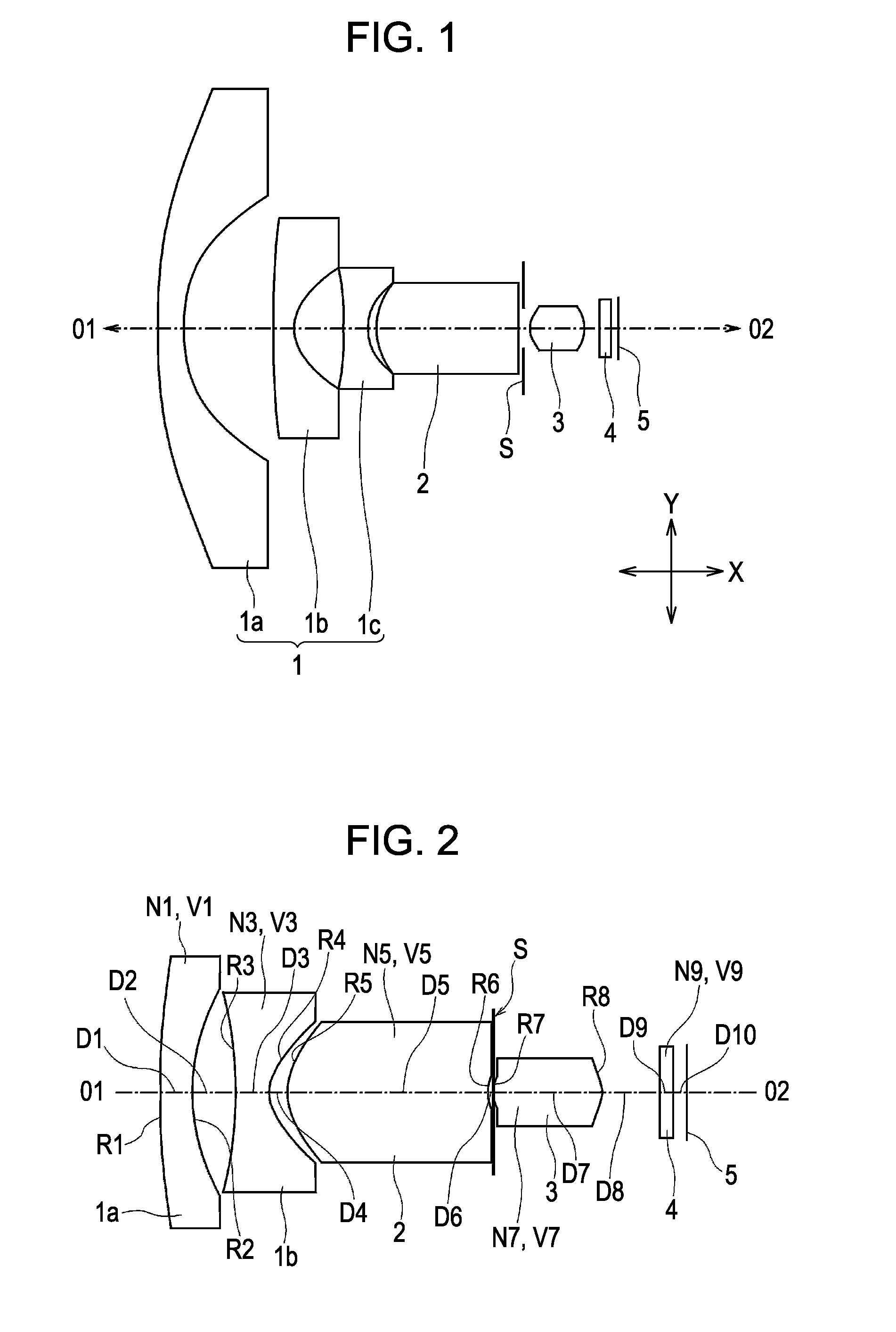
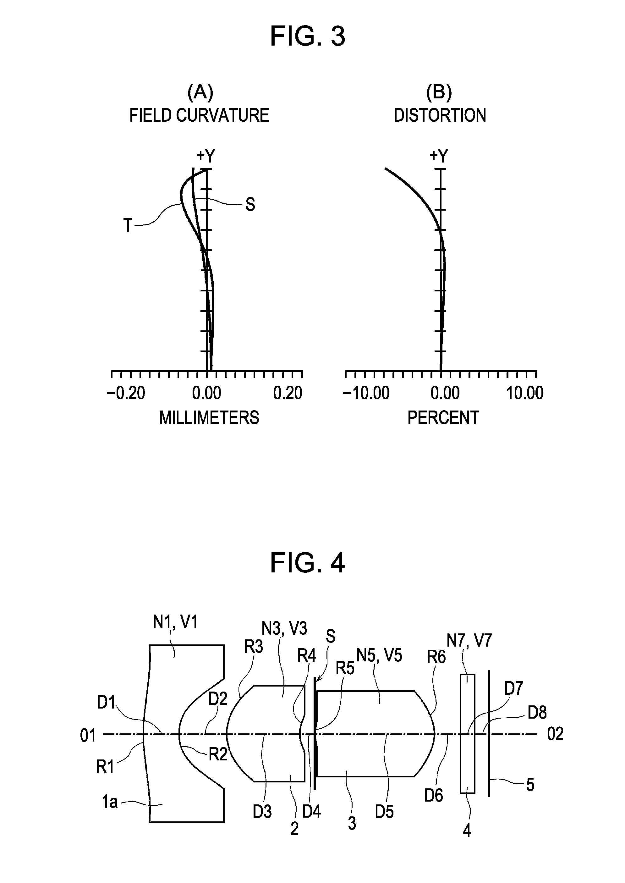
[0063]FIGS. 2, 4, 6, 8, 10, 12, and 13 show optical apparatuses according to the examples of the present invention. In the examples shown in the above-mentioned figures and examples not shown in the figures, reference symbols have the followin...


PUM


Abstract

[Object] To provide a high-brightness, small, low-cost optical apparatus which covers a wide-angle to super-wide-angle region and which reliably corrects various aberrations with a small number of lenses.
[Solving Means] At least one negative lens unit 1, a meniscus lens 2 that is convex on an object side, an aperture stop S, and a double-convex positive lens 3 are arranged in order from the object side. At least one of the lenses positioned on the object side of the aperture stop S and the positive lens 3 include respective aspherical surfaces. When va is an average Abbe number of all of the lenses excluding the meniscus lens, vb is an Abbe number of the meniscus lens, f is a focal length of the entire system, f12 is a combined focal length of the negative lens unit and the meniscus lens, ts is a distance between the aperture stop and the positive lens along an axis, L is a distance between a vertex of a lens surface nearest to the object side and a vertex of a lens surface nearest to the image side, t2 is a central thickness of the meniscus lens, θs is an incident angle of a chief ray that passes through the aperture stop at a maximum angle of view, 1.4<va/vb, 0<ts/L<0.1, 0.2<t2/L<0.5, −10<f12/f<−1.0, and 25°<θs<40° are satisfied.

Description

CROSS REFERENCE TO RELATED APPLICATION[0001]This is a continuation of International Application No. PCT / JP2006 / 314247, filed Jul. 19, 2006, which is incorporated herein by reference in its entirety.TECHNICAL FIELD[0002]The present invention relates to an optical apparatus capable of forming an image of an object on a light receiving plane at a wide angle.BACKGROUND ART[0003]Wide-angle lenses for capturing a wide field of view are used in the field of on-vehicle cameras and surveillance cameras. In addition, progress in image processing techniques has made it possible to correct distortion of images in real time, and there have been increasing demands for super-wide-angle lenses having a still wider field of view. In particular, in accordance with the problems of installation space, increase in the resolution of picture elements, and applications in various fields, there have been demands for small, high-resolution, and low-cost optical apparatuses.[0004]Such an optical apparatus is ...

Claims


Application Information

Patent Timeline
IPC IPC(8): G02B3/00
CPCG02B13/18G02B13/06
Inventor YAMASHITA, TATSUMAROMATSUO, EIKI
Owner ALPS ALPINE CO LTD
Why Eureka
Try Eureka