Fan system and starting method thereof

a fan system and fan technology, applied in the direction of motor/generator/converter stopper, dynamo-electric converter control, instruments, etc., can solve the problems of poor contact, direct influence on the reliability and lifetime of electronic equipment, damage to customers, etc., to prevent and suppress the noise of positive or negative spikes

Active Publication Date: 2008-06-05
DELTA ELECTRONICS INC
View PDF7 Cites 6 Cited by
  • Summary
  • Abstract
  • Description
  • Claims
  • Application Information

AI Technical Summary

Benefits of technology

[0021]As mentioned above, the fan system and the starting method thereof according to the invention include the following features. The start controlling unit synchronously outputs the first enabling signal or outputs the first enabling signal in sequence according to the start signal, and the fan device in sequence or synchronously outputs the driving signal to synchronously start the fans or start the fans in sequence according to the first enabling signal. Consequently, the start controlling unit can function to turn on or off the overall fan device, and can synchronously start the fans or start the fans in sequence. In addition, it is possible to ensure that no electric arc is generated at the contacts between the pins and the connector, and it is also possible to prevent the positive or negative spike noise from being transmitted to the controlling device and the fan device through the pins. In addition, the isolation protecting unit can effective suppress the spike voltage or inrush current generated by the main power circuit at the fan device end when the controlling device transmits the driving signals to the fan device, and suppress the spike noise generated at the instant when the fan device is started.

Problems solved by technology

Therefore, the heat dissipating function directly influences the reliability and the lifetime of the electronic apparatus.
When the user improperly swaps the fan, the pins 113 of the hot-swap controlling device 11 are easy to be bent, and the problem of the poor contact may rise due to the reduced terminal with the connector C1.
At the moment when the fan system is being started, an inrush current, a spike voltage or a spike noise may be generated between the fan system and the connector C1 of the customer system end SB1, or even a spark phenomenon (i.e., an electric arc) is generated, thereby damaging the customer system end SB1 or the fan system.
However, this method still cannot effectively and completely suppress the generation of the spike noise on the pins 113.
In addition, the functions of the customer system end SB1 becomes more complicated, the functional requirements on the fan system 1 are getting higher and higher.

Method used


Image

  • Fan system and starting method thereof
  • Fan system and starting method thereof
  • Fan system and starting method thereof

Examples


first embodiment

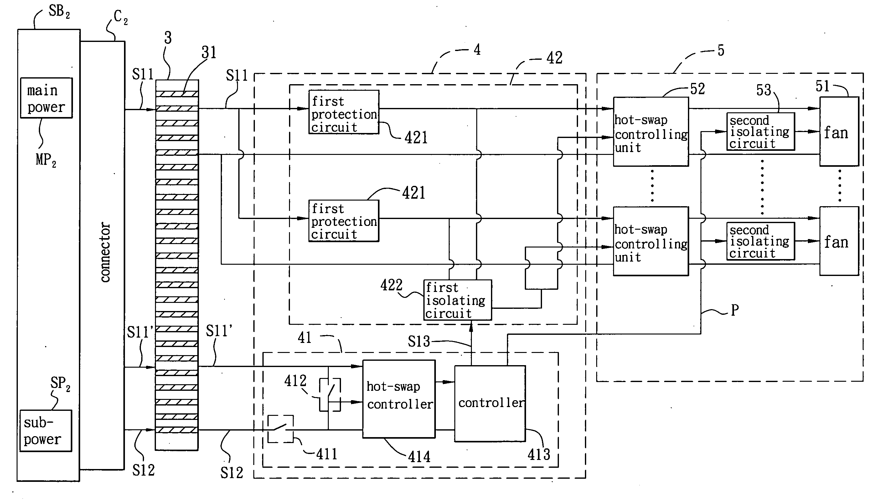
[0032]Referring to FIG. 3, a fan system according to the invention includes a connecting device 3, a controlling device 4 and a fan device 5. In practice, the fan system of this embodiment is electrically connected to a connector C2 of a customer system end SB2, the customer system end SB2 provides at least one of driving signals S11 and S11′ and a start signal S12 to the fan system through the connector C2, the driving signal S11 is generated by main power MP2 of the customer system end SB2, and the driving signal S11′ is generated by sub-power SP2. Herein, the customer system end SB2 provides the plurality of driving signals S11 and S11′. In addition, the driving signals S11 and S11′ and the start signal S12 in this embodiment have different voltage levels, and the start signal S12 is implemented as a low potential (voltage) signal or a ground signal. Herein, the start signal S12 is a ground signal.

[0033]The connecting device 3 of this embodiment has a plurality of pins 31, which ...

second embodiment

[0058]As shown in FIG. 8, the starting method for the fan system according to the invention will be described in the following with reference to the example of the fan system (see FIG. 7).

[0059]The starting method of the fan system in this example includes steps S4 to S6.

[0060]In step S4, at least one of driving signals S21 and S21′ and a start signal S22 are received.

[0061]In step S5, first enabling signals S23 are generated according to the start signal S22 in sequence. In this embodiment, the start signal S22 is a low potential (voltage) signal or a ground signal, and the first enabling signals S23 are generated by the controlling device 8 according to the start signal S22 in sequence.

[0062]In step S6, the driving signals S21 and S21′ are transmitted according to the first enabling signals S23 in sequence and the fans are driven in sequence. The driving signal S21 is transmitted by the controlling device 8 according to the first enabling signals S23.

[0063]In summary, the fan syst...


PUM


Abstract

A fan system includes a connecting device, a controlling device and a fan device. The connecting device has a plurality of pins receiving at least one driving signal and a start signal. The control device is electrically connected to the pins of the connecting device and has a start control unit. The start control unit generates a first enabling signal in accordance with the start signal. The control device synchronously outputs the first enabling signal and the driving signal. The fan device is electrically connected to the control device and has a plurality of fans. The fan device synchronously transmits the driving signal to the fans and synchronously drives the fans to rotate in accordance with the first enabling signal.

Description

CROSS REFERENCE TO RELATED APPLICATIONS[0001]This Non-provisional application claims priority under 35 U.S.C. §119(a) on Patent Application No(s). 095144574 filed in Taiwan, Republic of China on Dec. 1, 2006, the entire contents of which are hereby incorporated by reference.BACKGROUND OF THE INVENTION[0002]1. Field of Invention[0003]The invention relates to a fan system and a starting method thereof and, in particular, relates to a fan system and a starting method thereof capable of starting fans synchronously or in sequence.[0004]2. Related Art[0005]With the high development of the technology, the requirements on the functions of an electronic apparatus are getting higher and higher, the number of the used electronic elements and the degree of integration are getting higher and higher, and the need to dissipate heat is increased. Therefore, the heat dissipating function directly influences the reliability and the lifetime of the electronic apparatus.[0006]A fan is frequently used t...

Claims


Application Information

Patent Timeline
Patent Type & Authority Applications(United States)
IPC IPC(8): H02P7/29
CPCF04D27/004F04D25/166Y02B30/70
Inventor CHEN, CHIEN-HUAWEI, CHIN-PINTSENG, WEI-SHUO
Owner DELTA ELECTRONICS INC
Why Eureka
Try Eureka