Mounting assembly with positive stop for actuator arm

Active Publication Date: 2008-06-12
SWAN RICHARD E
View PDF29 Cites 38 Cited by
  • Summary
  • Abstract
  • Description
  • Claims
  • Application Information

AI Technical Summary

Benefits of technology

[0013]The mounting assembly of the present invention further includes a shoulder formation positioned on the boss formation adjacent the position on the mount where the actuator arm is received. The shoulder extends upwardly from the body of the mounting assembly and is positioned in such a manner that the shoulder prevents over rotation of the actuator arm beyond the fully disengaged position. As was the case in the prior art, the actuator arm is often over rotated when the user opens the mounting lever assembly. The result of such over rotation often causes the camming foot to interfere with easy installation and/or removal of the mounting assembly relative to the dovetail rail. The shoulder formation of the present invention overcomes this difficulty by providing a positive stop for the actuator arm once it reaches the fully open position. In the fully open position, with the actuator arm against the shoulder formation, the camming foo

Problems solved by technology

The result of such over rotation often causes the camming foot to interfere with eas

Method used


Image

  • Mounting assembly with positive stop for actuator arm
  • Mounting assembly with positive stop for actuator arm
  • Mounting assembly with positive stop for actuator arm

Examples


Embodiment Construction

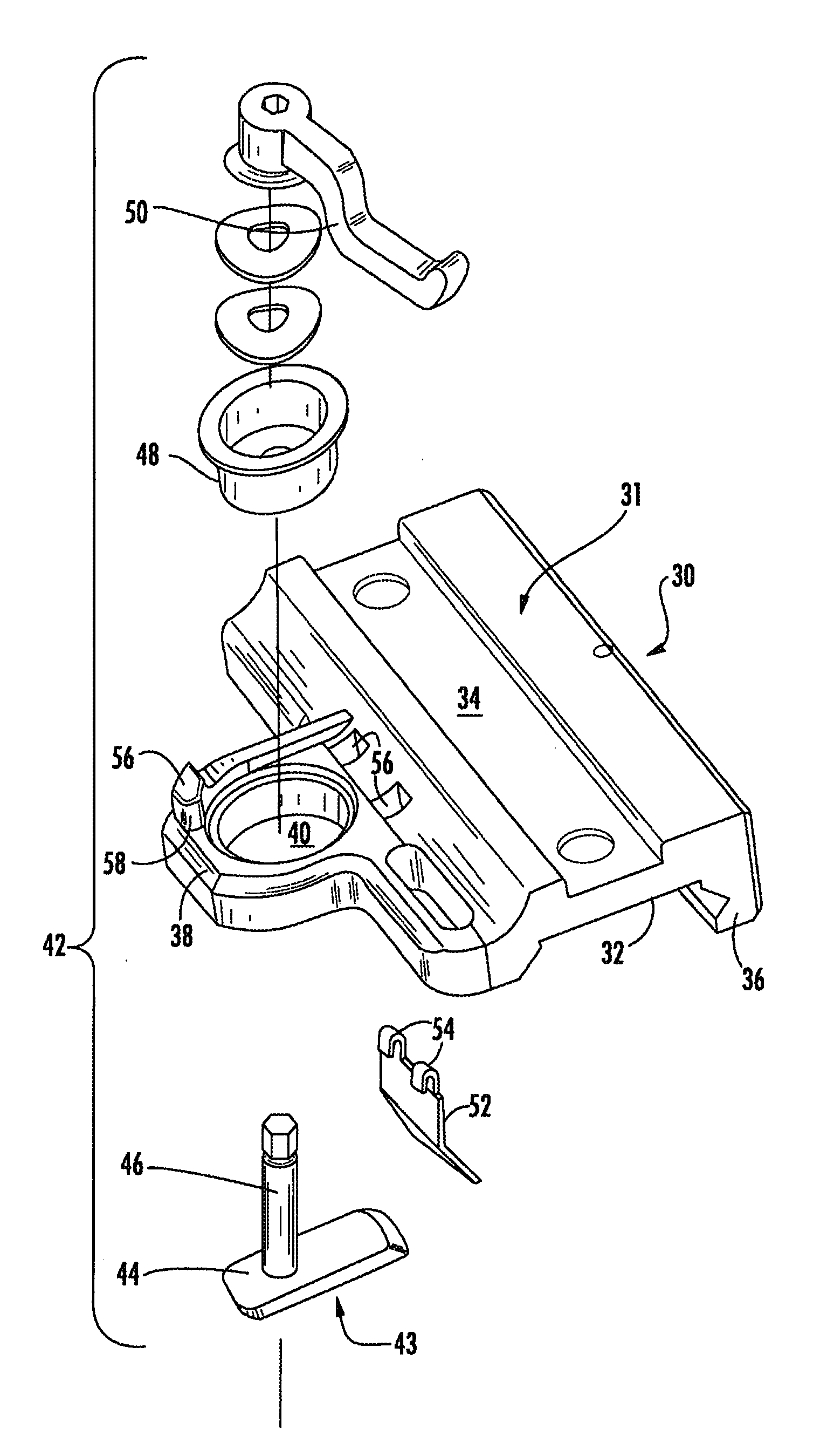
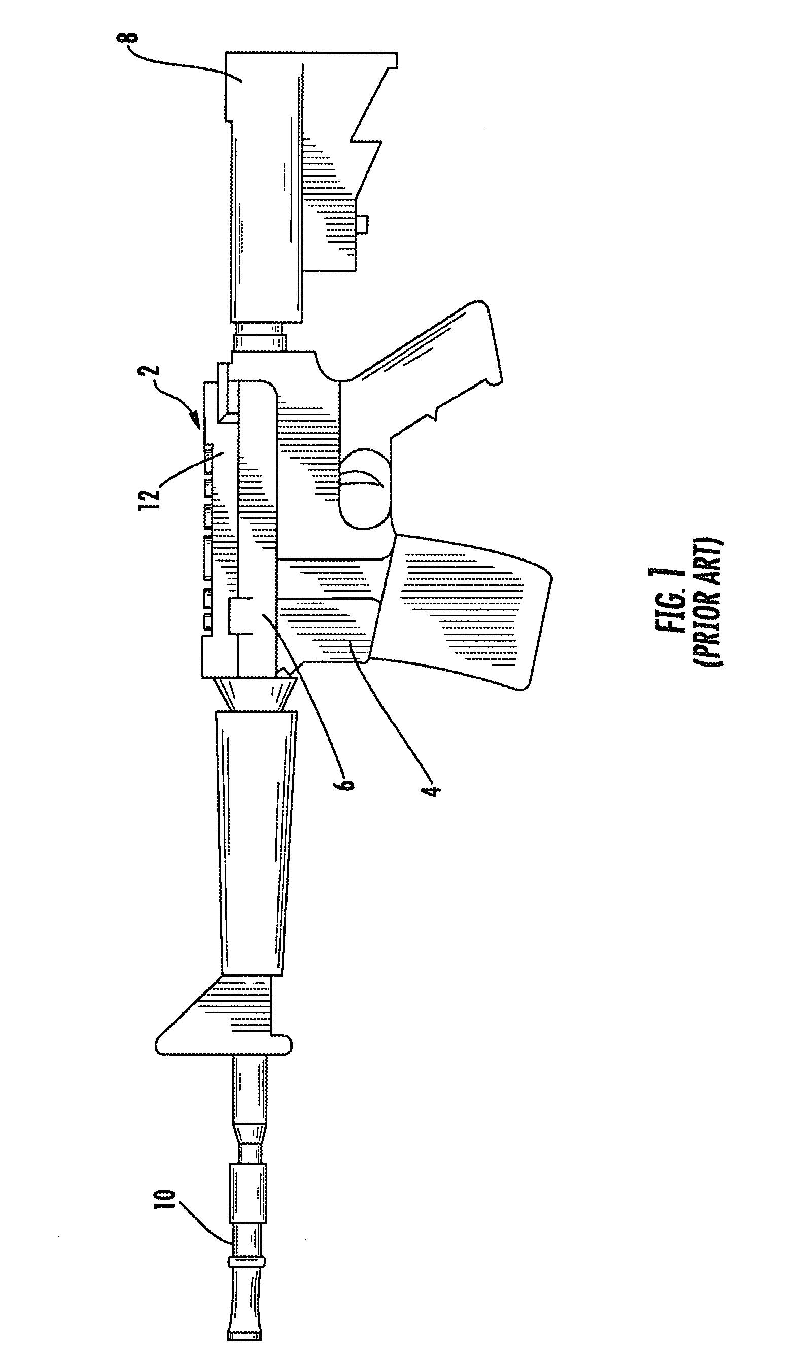
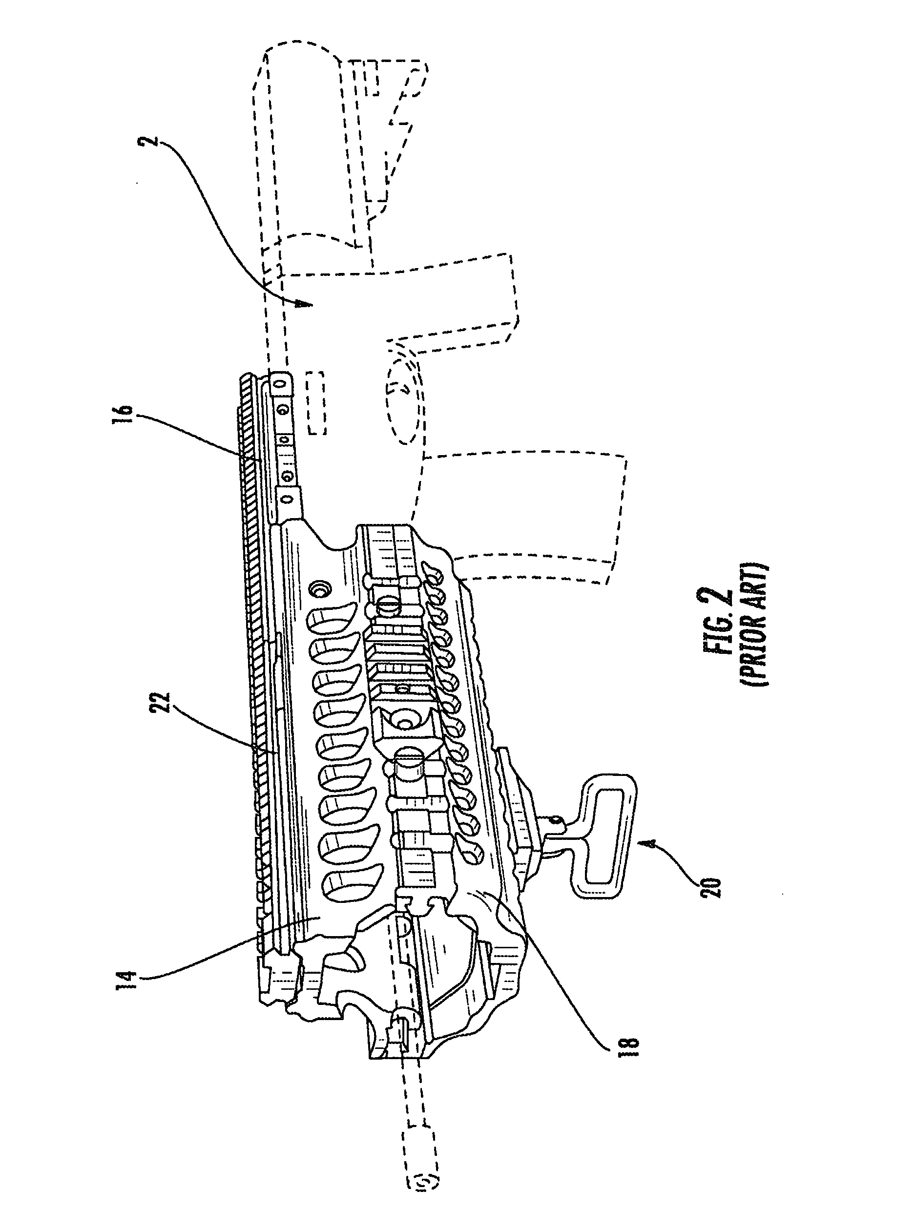
[0024]Now referring to the drawings, the mounting assembly is shown and generally illustrated at 30 in FIGS. 3-5. The mounting assembly 30 is configured to be releasably attached to a standard dovetail rail profile 22 as is depicted in FIGS. 1 and 2, and includes a positive index that corresponds to both the fully opened and fully closed positions. The mounting assembly 30 of the present invention is particularly suited for use in connection with any firearm that utilizes a standard dovetail rail system. Further, the mounting assembly 30 is configured in substantially the same manner as a traditional prior art mounting interface devices. The mounting assembly 30 includes a lower clamping portion that engages the dovetail rail 22 found on most modern combat weapons and an upper accessory interface portion that can take on a variety of configurations depending on the accessory that is to be mounted thereon.

[0025]Turning now to FIG. 3, as can be seen, the mounting assembly 30 includes ...


PUM


Abstract

An improved mounting assembly is provided that is configured to be releasably mounted onto a standard dovetail rail profile and includes a positive index that corresponds to a fully opened position. The mounting assembly includes a boss formation that extends from one side thereof. A camming member and an actuator arm are installed into the boss formation and serve as a means for engaging and disengaging the mounting assembly relative to the dovetail rail. A shoulder formation is provided on the boss formation adjacent the actuator arm and extends upwardly such that the shoulder prevents over rotation of the actuator arm allowing the actuator arm to be positioned in a fully disengaged, open position where it will not interfere with removal or installation of the mounting assembly relative to the rail.

Description

CROSS-REFERENCE TO RELATED APPLICATIONS[0001]This application is related to and claims priority from earlier filed U.S. Provisional Patent Application No. 60 / 869,337, filed Dec. 11, 2006.BACKGROUND OF THE INVENTION[0002]The present invention relates generally to accessory mounting assemblies for combat weapons such as the modular integrated accessory systems found on most modern combat weapons. More specifically, the present invention relates to a mounting assembly including a shoulder formation that prevents over rotation of the actuator arm when moved to the open position.[0003]As the field of combat and commercial weaponry expands, numerous add-on enhancements have become available for attachment to standard firearms, thereby significantly upgrading the capability of the firearm. Of particular interest in the area of combat weapons is the well-known M16 / M4 weapon system (M16 and M4 are trademarks of Colt Defense, Inc.). The M16 has been in service for a number of years and will c...

Claims


Application Information

Patent Timeline
IPC IPC(8): F41C27/00
CPCF41G11/003F41G1/387
Inventor SWAN, RICHARD E.
Owner SWAN RICHARD E
Why Eureka
Try Eureka