Ice dispensing and detecting apparatus

a detection apparatus and ice dispenser technology, applied in the field of refrigerator ice dispensers, can solve the problems of inconvenient use, inconvenient ice dispensing, difficult to consistently transfer ice pieces from storage bins to dispensing chutes, etc., and achieve the effect of improving the dispensing of a measured amount of ice pieces

Active Publication Date: 2008-06-12
WHIRLPOOL CORP
View PDF24 Cites 67 Cited by
  • Summary
  • Abstract
  • Description
  • Claims
  • Application Information

AI Technical Summary

Benefits of technology

[0011]Accordingly, the present invention is directed to an ice dispenser for a

Problems solved by technology

One problem with conventional ice dispensing systems is the inconsistency of the ice dispensing.
The refrigerator may initially dispense one cube and then suddenly dispense several cubes, which is undesirable for a user.
This problem is especially manifested when dispensing crescent-shaped ice pieces.
The different orientations make it difficult to consistently transfer ice pieces from the storage bin to the dispensing chute.
Additionally, the orientation of the crescent-shaped ice pieces in the chute can lead to jamming in the chute, in which case ice pieces cannot be dispensed.
One disadvantage of this system is that there is no assurance that an accurate quantity of ice is dispensed.
Moving parts add complexity to the design and manufacturing of the system and potentially decrease its reliability.
This design is not well suited for the dispensing of cubed ice.
The spokes of

Method used


Image

  • Ice dispensing and detecting apparatus
  • Ice dispensing and detecting apparatus
  • Ice dispensing and detecting apparatus

Examples


second embodiment

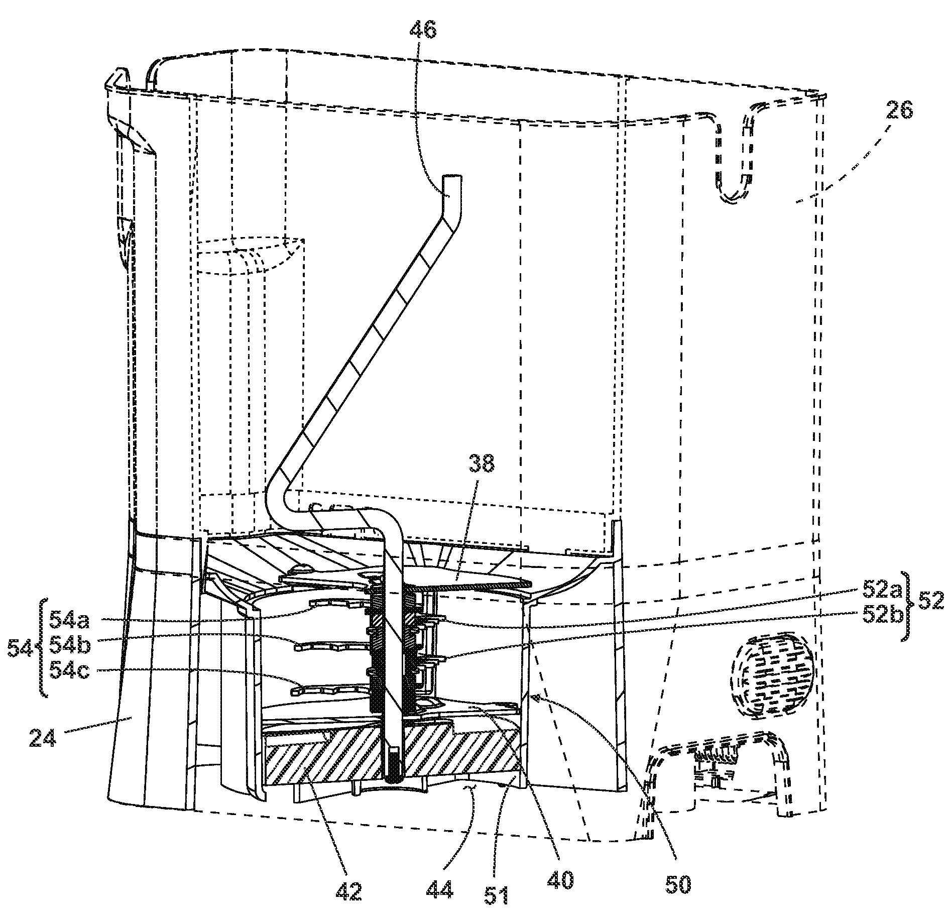
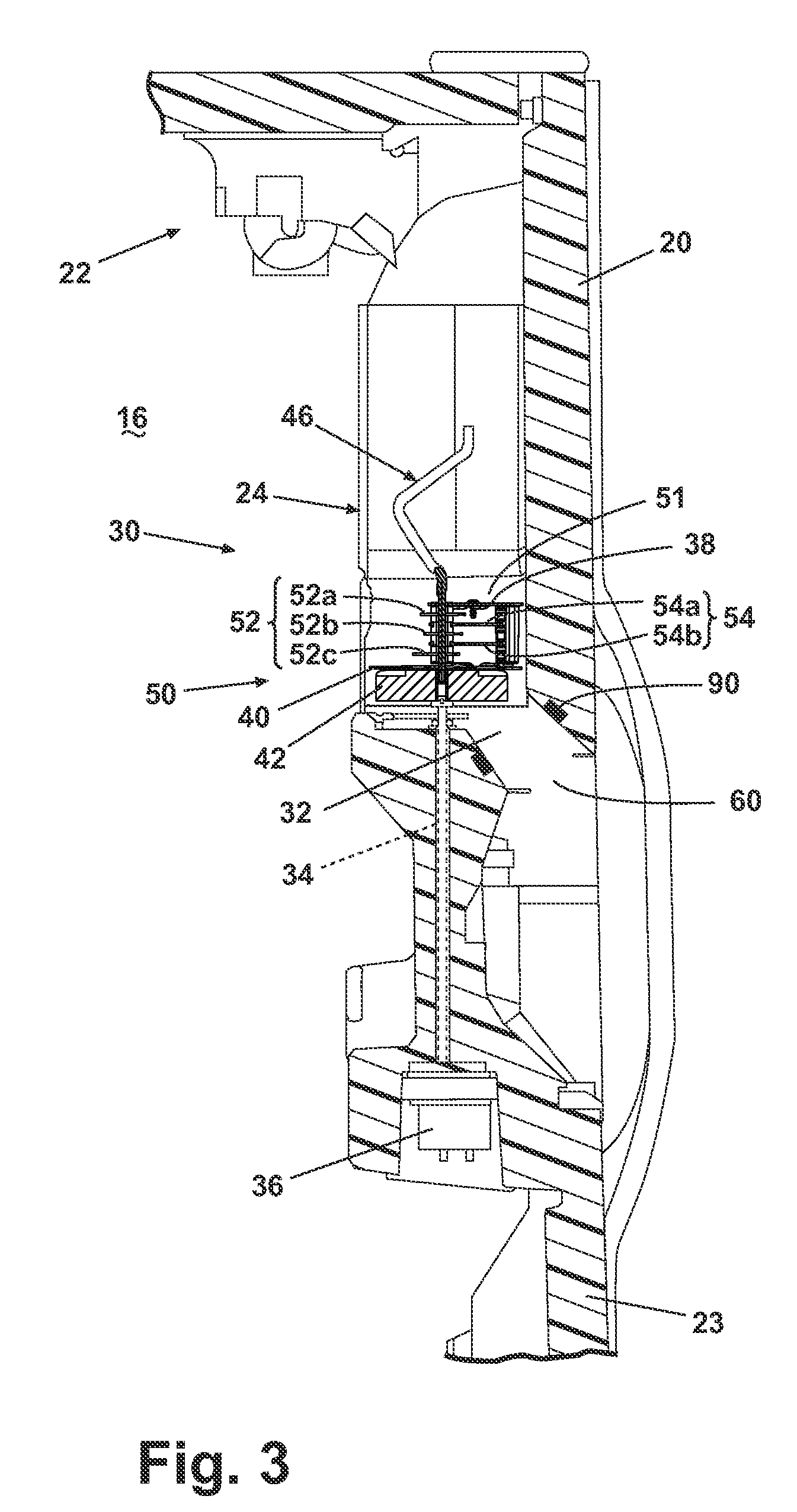
[0043]In one embodiment of the invention, the ice crushing system 50 comprises two fixed ice crusher blades 52a and 52b and three sets of rotating ice crusher blades 54a, 54b, and 54c. In a second embodiment, the ice crushing system 50 comprises one fixed ice crusher blade 52a and two sets of rotating ice crusher blades, 54a and 54b. Using the first configuration, the performance, as measured in output of ice pieces per minute, is higher but the ice crushing system 50 typically occupies a greater amount of space in the bottom ice bin member 28. Using the second configuration, the performance is lower but the ice crushing system 50 typically occupies a smaller space in the bottom ice bin member 28. Other combinations of fixed ice crusher blades 52 and rotating ice crusher blades 54 are possible without altering the function of the ice crushing system 50.

[0044]When crushed ice pieces are requested by a user, the motor 36 is actuated and the shaft 34 rotates, thereby moving the rotatin...

first embodiment

[0066]FIG. 10 discloses an alternative embodiment of the ice dispensing system 130. In this embodiment, the bottom ice bin member 128 further comprises an ice shaving system 70. The ice shaving system 70 is positioned adjacent to the ice crushing system 150 and functions to shave ice pieces to be dispensed. The ice dispensing system 130 comprises the same components as the In operation, an agitator 146 is rotated to move ice pieces into the ice dispensing system 130. Ice pieces may either be crushed by an ice crushing system 150 or uncrushed and separated by the metering device. Crushed ice pieces or uncrushed individual ice pieces are then dispensed through the ice dispensing chute. A shaved ice agitator 72 is disposed within the ice shaving system 70. When the shaved ice agitator 72 rotates, ice pieces are moved into the ice shaving system 70. The ice shaving system 70 typically does not include a metering device. Alternatively, the metering device 42 could be provided solely in ...


PUM


Abstract

The present invention relates to an ice dispenser apparatus having an ice storage bin removably mounted to the refrigerator for receiving and storing ice pieces from an ice maker, a metering device for separating individual ice pieces, and a sensing device for detecting the presence of ice pieces. Actuation of a motor causes the metering device to separate individual ice pieces and the sensing device detects ice pieces before, after, or during dispensing.

Description

BACKGROUND OF THE INVENTION[0001]1. Field of the Invention[0002]The invention relates to an ice dispenser for a refrigerator and more particularly to measured dispensing of ice pieces and sensing of dispensed ice pieces.[0003]2. Description of Related Art[0004]Ice dispensing systems for use in a home refrigerator are commonly known. A typical ice dispensing system includes an ice storage bin for receiving and storing ice pieces from an ice maker. The ice storage bin typically has an agitator to prevent the formation of large ice chunks. When a user requests ice, rotation of the agitator also functions to move ice pieces through an opening in the ice storage bin to be dispensed through a chute. The dispensed ice is usually in the form of ice cubes, crushed ice, shaved ice, or crescent-shaped ice. The ice dispensing system may be disposed within the freezer compartment of the refrigerator or may be mounted in a refrigerator closure member or door. U.S. Pat. No. 6,082,130, to Pastryk e...

Claims


Application Information

Patent Timeline
IPC IPC(8): F25C5/00F25D11/00
CPCF25C5/005F25C5/046F25C5/182F25C2700/08F25C2500/08F25C2600/04F25C2400/08F25C5/22
Inventor FISCHER, MARCUS ROLANDSIWEK, AMY LAURENCHASE, KEVIN MICHAELKOENIGSKNECHT, TONY LEEJEFFERY, RANDELL LEEBASHARK, LARRY THOMASFOUNTAIN, JORDAN ROBERTDAWSON, BRANDON MICHAELMCCOLLUM, RYAN DEANSCHWARTZ, MATTHEW RUSSEL
Owner WHIRLPOOL CORP
Why Eureka
Try Eureka